Chapter: Electrical machines : Magnetic Circuits and Magnetic Materials
Laws Governing Magnetic Circuits
Laws Governing Magnetic Circuits
1. Magnetic flux(ϕ):
The magnetic lines of force produced by a magnet is called magnetic flux. It is denoted by ϕ and its unit is Weber.
1 weber = 108 lines of force
2. Magnetic field strength
This is also known as field intensity, magnetic intensity or magnetic field, and is represented by the letter H. Its unit is ampere turns per metre.
H= Ampere turns / Length
H = NI/l AT/m
3.Flux density
The total number of lines of force per square metre of the cross-sectional area of the magnetic core is called flux density, and is represented by the symbol B. Its SI unit (in the MKS system) is testa (weber per metre square).
B= ϕ/a Wb/m2 or Tesla
where
ϕ -total flux in webers
A - area of the core in square metres
B - flux density in weber/metre square.
4 .Magneto-Motive Force
The amount of flux density setup in the core is dependent upon five factors - the current, number of turns, material of the magnetic core, length of core and the cross-sectional area of the core. More current and the more turns of wire we use, the greater will be the magnetizing effect. We call this product of the turns and current the magneto motive force (mmf), similar to the electromotive force (ernf).
MMF = NI ampere - turns
Where mmf is the magneto motive force in ampere turns
N is the number of turns, A.
5. Magnetic Reluctance
In the magnetic circuit there is something analogous to electrical resistance, and is called reluctance, (symbol S). The total flux is inversely proportional to the reluctance and so if we denote mmf by ampere turns. we can write
S µ l/a
S=Kl /a
K = Constant of proportionality
= Reciprocal of absolute permeability of material
S = l / μa = l / μo µra A/Wb
Where, S - reluctance
I - length of the magnetic path in meters
μo- permeability of free space
µr - relative permeability
a - cross-sectional area
6. Residual Magnetism
It is the magnetism which remains in a material when the effective magnetizing force has been reduced to zero.
7. Magnetic Saturation
The limit beyond which the strength of a magnet cannot be increased is called magnetic saturation.
8. End Rule
According to this rule the current direction when looked from one end of the coil is in clock wise direction then that end is South Pole. If the current direction is in anti clock wise direction then that end is North Pole.
9. Len’s Law
When an emf is induced in a circuit electromagnetically the current set up always opposes the motion or change in current which produces it.
10. Electro magnetic induction
Electromagnetic induction means the electricity induced by the magnetic field
Faraday's Laws of Electro Magnetic Induction
There are two laws of Faraday's laws of electromagnetic induction. They are,
1) First Law
2) Second Law
First Law
Whenever a conductor cuts the magnetic flux lines an emf is induced in the conductor.
Second Law
The magnitude of the induced emf is equal to the rate of change of flux-linkages.
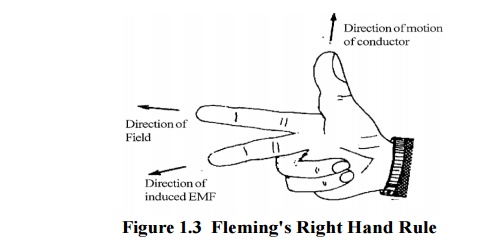
11. Fleming's Right Hand Rule
This rule is used to find out the direction of dynamically induced emf. According to the rule hold out the right hand with the Index finger middle finger and thumb at the right angels to each others. If the index finger represents the direction of the lines of flux, the thumb points in the direction of motion then middle finger points in the direction of induced current.

Related Topics