Chapter: Transmission and Distribution : Transmission Line Parameters
Inductance of a Single Phase Two-Wire Line
INDUCTANCE OF A SINGLE PHASE TWO-WIRE LINE
A single phase line consists of two parallel conductors which form a rectangular loop of one turn.
When an alternating current flows through such a loop, a changing magnetic flux is set up. The changing flux links the loop and hence the loop (or single phase line) possesses inductance. It may appear that inductance of a single phase line is negligible because it consists of a loop of one turn and the flux path is through air of high reluctance. But as the X –sectional area of the loop is very **large, even for a small flux density, the total flux linking the loop is quite large and hence the line has appreciable inductance.
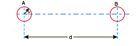
Consider a single phase overhead line consisting of two parallel conductors A and B spaced d metres apart as shown in Fig. 9.7. Conductors A and B carry the same amount of current ( i.e. IA = IB ), but in the opposite direction because one forms the return circuit of the other.
IA+IB = 0
In order to find the inductance of conductor A (or conductor B), we shall have to consider the flux linkages with it. There will be flux linkages with conductor A due to its own current IA and also A due to the mutual inductance effect of current IB in the conductor B Flux linkages with conductor A due to its own current

Flux linkages with conductor A due to current IB

Total flux linkages with conductor A is
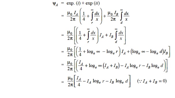
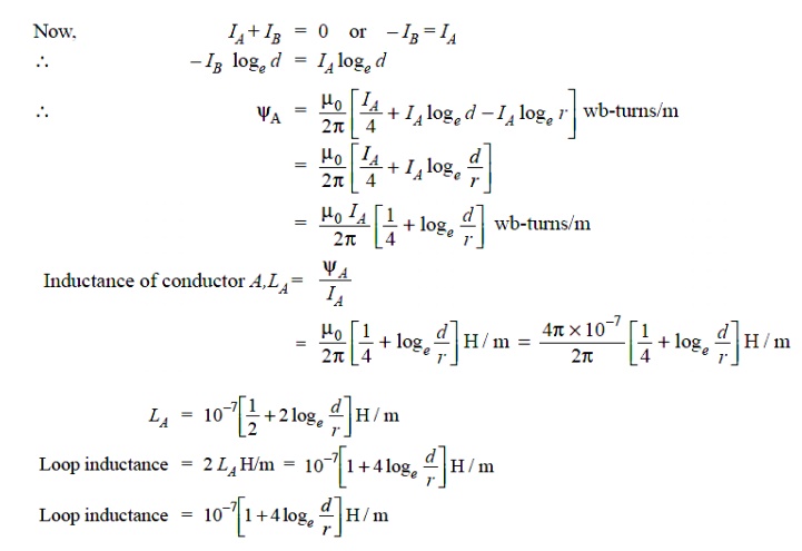
Note that eq. ( ii) is the inductance of the two-wire line and is sometimes called loop inductance. However, inductance given by eq. ( i) is the inductance per conductor and is equal to half the loop inductance.
1. INDUCTANCE OF A 3-PHASE OVERHEAD LINE
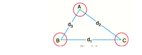
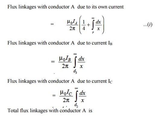
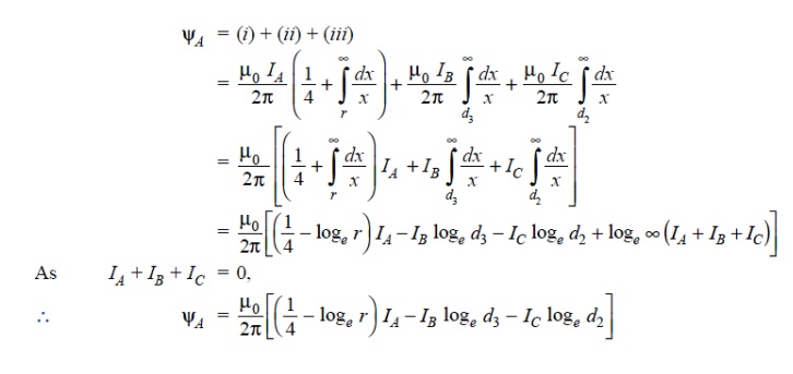
Fig. shows the three conductors A, B and C of a 3-phase line carrying currents IA , IB and IC respectively. Let d 1 , d2 and d3 be the spacings between the conductors as shown. Let us further assume that the loads are balanced i.e. IA + IB + IC = 0. Consider the flux linkages with conductor There will be flux linkages with conductor A due to its own current and also due to the mutual inductance effects of IB and IC
2. SYMMETRICAL SPACING
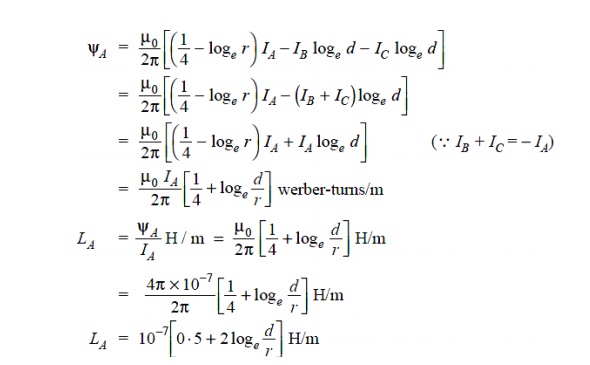
If the three conductors A, B and C are placed symmetrically at the corners of an equilateral triangle of side d, then, d1 = d2 = d3 = d. Under such conditions, the flux Derived in a similar way, the expressions for inductance are the same for conductors B and C.
3. UNSYMMETRICAL SPACING
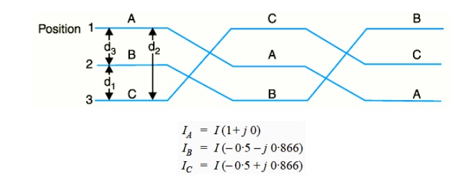
When 3-phase line conductors are not equidistant from each other, the conductor spacing is said to be unsymmetrical. Under such conditions, the flux linkages and inductance of each phase are not the same. A different inductance in each phase results in unequal voltage drops in the three phases even if the currents in the conductors are balanced. Therefore, the voltage at the receiving end will not be the same for all phases. In order that voltage drops are equal in all conductors, we generally interchange the positions of the conductors at regular intervals along the line so that each conductor occupies the original position of every other conductor over an equal distance. Such an exchange of positions is known as transposition. Fig.shows the transposed line. The phase conductors are designated as A, B and C and the positions occupied are numbered 1, 2 and 3. The effect of transposition is that each conductor has the same average inductance.
Fig. shows a 3-phase transposed line having unsymmetrical spacing. Let us assume that each of the three sections is 1 m in length. Let us further assume balanced conditions i.e.,
IA + IB +IC = 0
Let the line currents be :
As proved above, the total flux linkages per metre length of conductor A is

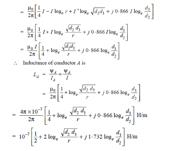
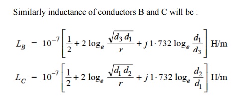
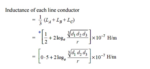
If we compare the formula of inductance of an un symmetrically spaced transposed line with that of symmetrically spaced line, we find that inductance of each line conductor in the two cases will be equal if

The distance d is known as equivalent equilateral spacing for un symmetrically transposed line
Related Topics