Chapter: High Voltage Engineering : Measurement of High Voltage and High Currents
Impulse Voltage Measurements Using Voltage Dividers
Impulse Voltage Measurements
Using Voltage Dividers
If the
amplitudes of the impulse voltage is not high and is in the range of a few
kilovolts, it is possible to measure them even when these are of short duration
by using CROS. However, if the voltages to be measured are of high magnitude of
the order of megavolts which normally is the case for testing and research
purposes, various problems arise. The voltage dividers required are of special
design and need a thorough understanding of the interaction present in these
voltage dividing systems. The voltage generator G is connected to a test object—T
through a lead L.
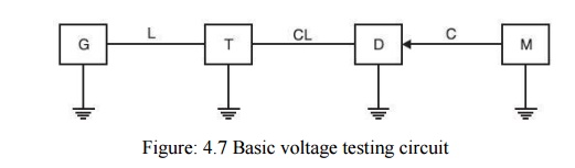
These
three elements form a voltage generating system. The lead L consists of a lead
wire and a resistance to damp oscillation or to limit short-circuit currents if
of the test object fails. The measuring system starts at the terminals of the
test object and consists of a connecting lead CL to the voltage divider D. The
output of the divider is fed to the measuring instrument (CRO etc.) M. The
appropriate ground return should assure low voltage drops for even highly
transient phenomena and keep the ground potential of zero as far as possible.
It is to
be noted that the test object is a predominantly capacitive element and thus
this forms an Oscillatory circuit with the inductance of the load. These
oscillations are likely to be excited by any steep voltage rise from the
generator output, but will only partly be detected by the voltage divider. A
resistor in series with the connecting leads damps out these oscillations. The
voltage divider should always be connected outside the generator circuit
towards the load circuit (Test object) for accurate measurement. In case it is
connected within the generator circuit and the test object discharges (chopped
wave) the whole generator including voltage divider will be discharged by this
short circuit at the test object and thus the voltage divider is loaded by the
voltage drop across the lead L. As a result, the voltage measurement will be
wrong. Yet for another reason, the voltage divider should be located away from
the generator circuit. The dividers cannot be shielded against external fields.
All objects in the vicinity of the divider which may acquire transient
potentials during a test will disturb the field distribution and thus the
divider performance. Therefore, the connecting lead CL is an integral part of
the potential divider circuit. In order to avoid electromagnetic interference
between the measuring instrument M and C the high voltage test area, the length
of the delay cable should be adequately chosen. Very short length of the cable
can be used only if the measuring instrument has high level of electromagnetic
compatibility (EMC). For any type of voltage to be measured, the cable should
be co-axial type. The outer conductor provides a shield against the electrostatic
field and thus prevents the penetration of this field to the inner conductor.
Even though, the transient magnetic fields will penetrate into the cable, no
appreciable voltage is induced due to the symmetrical arrangement. Ordinary
coaxial cables with braided shields may well be used for d.c. and a.c.
voltages. However, for impulse voltage measurement double shielded cables with
predominantly two insulated braided shields will be used for better accuracy.
During
disruption of test object, very heavy transient current flow and hence the
potential of the Ground may rise to dangerously high values if proper earthling
is not provided. For this, large metal sheets of highly conducting material
such as copper or aluminum are used. Most of the modern high voltage
laboratories provide such ground return along with a Faraday Cage for a
complete shielding of the laboratory. Expanded metal sheets give similar
performance. At least metal tapes of large width should be used to reduce the
impedance.
Voltages
dividers for a.c., d.c. or impulse voltages may consist of resistors or
capacitors or a convenient combination of these elements. Inductors are
normally not used as voltage dividing elements as pure inductances of proper
magnitudes without stray capacitance cannot be built and also these inductances
would otherwise form oscillatory circuit with the inherent capacitance of the
test object and this may lead to inaccuracy in measurement and high voltages in
the measuring circuit. The height of a voltage divider depends upon the flash
over voltage and this follows from the rated maximum voltage applied.
Now, the
potential distribution may not be uniform and hence the height also depends
upon the design of the high voltage electrode, the top electrode. For voltages
in the megavolt range, the height of the divider becomes large. As a thumb rule
following clearances between top electrode and ground may be assumed 2.5 to 3
meters/MV for d.c. voltages.2 to 2.5 m/MV for lightning impulse voltages. More
than 5 m/MV rms for a.c. voltages. More than 4 m/MV for switching impulse
voltage.The potential divider is most simply represented by two impedances Z1
and Z2 connected in series and the sample voltage required for measurement is
taken from across Z2, FIG. 4.8.If the voltage to be measured is V1 and sampled
voltage V2, then
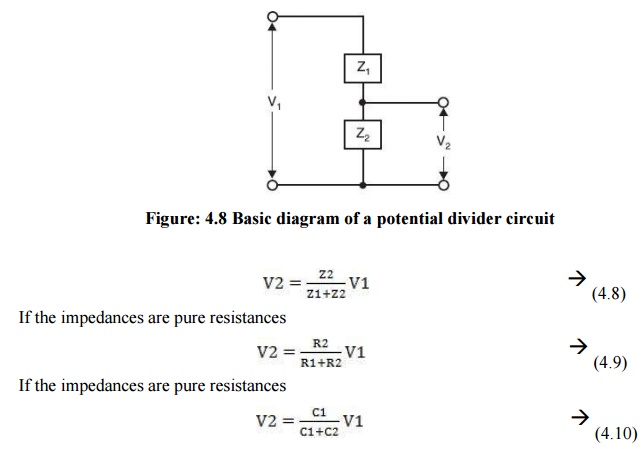
The
voltage V2 is normally only a few hundred volts and hence the value
of Z2 is so chosen that V2 across it gives sufficient
deflection on a CRO. Therefore, most of the voltage drop is available across
the impedance Z1 and since the voltage to be measured is in megavolt
the length of Z1 is large which result in inaccurate measurements
because of the stray capacitances associated with long length voltage dividers
(especially with impulse voltage measurements) unless special precautions are
taken. On the low voltage side of the potential dividers where a screened cable
of finite length has to be employed for connection to the oscillograph other
errors and distortion of wave shape can also occur.
Related Topics