Chapter: High Voltage Engineering : Measurement of High Voltage and High Currents
Electrostatic Voltmeter - Measurement of High Voltage and Currents

Electrostatic Voltmeter
The
electric field according to Coulomb is the field of forces. The electric field
is produced by voltage and, therefore, if the field force could be measured,
the voltage can also be measured. Whenever a voltage is applied to a parallel
plate electrode arrangement, an electric field is set up between the plates. It
is possible to have uniform electric field between the plates with suitable
arrangement of the plates. The field is uniform, normal to the two plates and
directed towards the negative plate. If A is the area of the plate and E is the
electric field intensity between the plates ε the permittivity of the medium
between the plates, we know that the energy density of the electric field
between the plates is given as,

Consider
a differential volume between the plates and parallel to the plates with area A
and thickness dx, the energy content in this differential volume Adx i

Now force
F between the plates is defined as the derivative of stored electric energy
along the field direction i.e.,

Now E =
V/d where V is the voltage to be measured and d the distance of separation
between the plates. Therefore, the expression for force

Since the
two plates are oppositely charged, there is always force of attraction between
the plates. If the voltage is time dependant, the force developed is also time
dependant. In such a case the mean value of force is used to measure the
voltage. ThusElectrostatic voltmeters measure the force based on the above
equations and are arranged such that one of the plates is rigidly fixed whereas
the

other is
allowed to move. With this the electric field gets disturbed. For this reason,
the movable electrode is allowed to move by not more than a fraction of a
millimeter to a few millimeters even for high voltages so that the change in
electric field is negligibly small. As the force is proportional to square of
Vrms, the meter can be used both for a.c. and d.c voltage measurement.
The force
developed between the plates is sufficient to be used to measure the voltage.
Various designs of the voltmeter have been developed which differ in the
construction of electrode arrangement and in the use of different methods of
restoring forces required to balance the electrostatic force of attraction.
Some of the methods are
·
Suspension of moving electrode on one arm of a
balance.
·
Suspension of the moving electrode on a spring.
·
Pendulous suspension of the moving electrode.
·
Torsional suspension of moving electrode.
The small
movement is generally transmitted and amplified by electrical or optical
methods. If the electrode movement is minimized and the field distribution can
exactly be calculated, the meter can be used for absolute voltage measurement
as the calibration can be made in terms of the fundamental quantities of length
and force. From the expression for the force, it is clear that for a given
voltage to be measured, the higher the force, the greater is the precision that
can be obtained with the meter. In order to achieve higher force for a given
voltage, the area of the plates should be large, the spacing between the plates
(d) should be small and some dielectric medium other than air should be used in
between the plates.
If
uniformity of electric field is to be maintained an increase in area A must be
accompanied by an increase in the area of the surrounding guard ring and of the
opposing plate and the electrode may, therefore, become unduly large especially
for higher voltages. Similarly the gap length cannot be made very small as this
is limited by the breakdown strength of the dielectric medium between the
plates. If air is used as the medium, gradients upto5 kV/cm has been found
satisfactory. For higher gradients vacuum or SF6gas has been used. The greatest
advantage of the electrostatic voltmeter is its extremely low loading effect as
only electric fields are required to be set up. Because of high resistance of
the medium between the plates, the active power loss is negligibly small. The
voltage source loading is, therefore, limited only to their active power
required to charge the instrument capacitance which can be as low as a few pico
farads for low voltage voltmeters.
The
measuring system as such does not put any upper limit on the frequency of
supply to be measured. However, as the load inductance and the measuring system
capacitance form a series resonance circuit, a limit is imposed on the
frequency range. For low range voltmeters, the upper frequency is generally
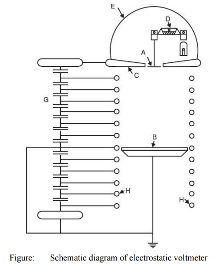
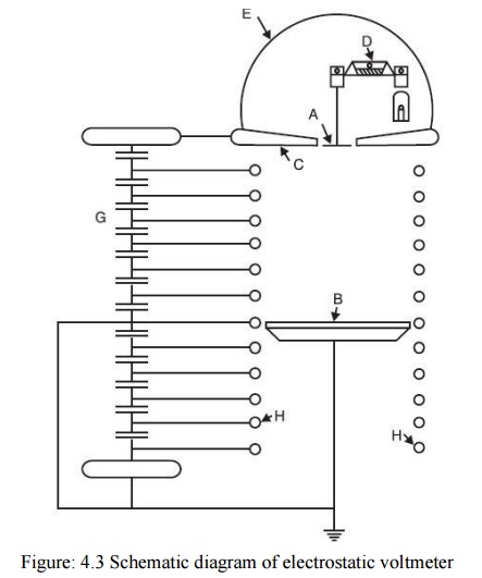
limited to a few MHz. Fig. 4.4 shows a schematic diagram of an absolute
electrostatic voltmeter. The hemispherical metal dome D encloses a sensitive
balance B which measures the force of attraction between the movable disc which
hangs from one of its arms and the lower plate P. The movable electrode M hangs
with a clearance of above 0.01 cm, in a central opening in the upper plate
which serves as a guard ring. The diameter of each of the plates is 1 metre.
Light reflected from a mirror carried by the balance beam serves to magnify its
motion and to indicate to the operator at a safe distance when a condition of
equilibrium is reached. As the spacing between the two electrodes is large
(about 100 cms for a voltage of about 300 kV), the uniformity of the electric
field is maintained by the guard rings G which surround the space between the
discs M and P. The guard rings G are maintained at a constant potential in
space by a capacitance divider ensuring a uniform spatial potential
distribution. When voltages in the range10 to 100 kV are measured, the accuracy
is of the order of 0.01 per cent. Hueter has used a pair of spheres of 100 cms
diameter for the measurement of high voltages utilizing the electrostatic
attractive force between them. The spheres are arranged with a vertical axis
and at spacing slightly greater than the sparking distance for the particular
voltage to be measured. The upper high voltage sphere is supported on a spring
and the extension of spring caused by the electrostatic force is magnified by a
lamp-mirror scale arrangement. An accuracy of 0.5 per cent has been achieved by
the arrangement.

Electrostatic
voltmeters using compressed gas as the insulating medium have been developed.
Here for a given voltage the shorter gap length enables the required uniformity
of the field to be maintained with electrodes of smaller size and a more
compact system can be evolved. One such voltmeter using SF6 gas has been used
which can measure voltages upto 1000 kV and accuracy is of the order of 0.1%.
The high voltage electrode and earthed plane provide uniform electric field
within the region of a 5 cm diameter disc set in a 65 cm diameter guard plane.
A weighing balance arrangement is used to allow a large damping mass. The gap
length can be varied between 2.5, 5 and10 cms and due to maximum working
electric stress of 100 kV/cm, the voltage ranges can be selected to 250 kV, 500
kV and 100 kV. With 100 kV/cm as gradient, the average force on the disc is
found to be0.8681 N equivalent to 88.52 gm wt. The disc movements are kept as
small as 1 μm by the weighing balance arrangement. The voltmeters are used for
the measurement of high a.c. and d.c voltages. The measurement of voltages
lower than about 50 volt is, however, not possible, as the forces become too
small.
Related Topics