Chapter: Cryptography and Network Security Principles and Practice : Network and Internet Security : Wireless Network Security
IEEE 802.11i Wireless LAN Security
IEEE 802.11i WIRELESS LAN SECURITY
There are two characteristics of a wired
LAN that are not inherent
in a wireless LAN.
1.
In order to transmit
over a wired LAN, a station
must be physically connected
to the LAN. On the other hand, with a wireless LAN, any station
within radio range of the other
devices on the LAN can transmit. In a sense,
there is a form
of authentication with a wired LAN
in that it requires some positive and presumably observable action to connect a station to a wired
LAN.
2.
Similarly, in order
to receive a transmission from a station that is part of a wired LAN, the receiving station
also must be attached to the wired LAN. On
the other
hand, with a wireless LAN, any station
within radio range can receive. Thus, a wired LAN provides a degree of privacy,
limiting reception of data to stations connected to the LAN.
These differences between wired and wireless
LANs suggest the increased need for robust security services and mechanisms for
wireless LANs. The original
specification included
a set of security features
for privacy and authentication
that
were quite weak. For privacy,
802.11 defined the Wired Equivalent
Privacy (WEP) algorithm. The privacy
portion of the 802.11 standard
contained major weak- nesses. Subsequent to the development of WEP, the 802.11i
task group has
developed a set of capabilities to address the WLAN security
issues. In order to accelerate the introduction of strong security
into WLANs, the Wi-Fi Alliance promulgated Wi-Fi Protected Access (WPA) as a Wi-Fi standard. WPA is a set of security
mechanisms that eliminates most 802.11 security
issues and was based on the current
state of the 802.11i standard. The final form of
the 802.11i standard is referred to as Robust Security Network (RSN). The Wi-Fi Alliance certifies
vendors in compliance with the full 802.11i specification under the WPA2 program.
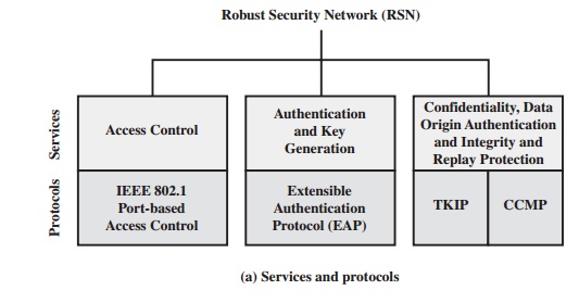
IEEE 802.11i Services
The 802.11i RSN security specification
defines the following services.
•
Authentication: A protocol is used to define an exchange between
a user and an AS that provides mutual authentication and generates
temporary keys to be used between
the client and the AP over the wireless link.
•
Access control:1 This function
enforces the use of the authentication function, routes the messages properly, and facilitates key exchange. It can work with a variety
of authentication protocols.
•
Privacy
with message integrity: MAC-level data (e.g., an LLC PDU) are encrypted along with a message integrity
code that ensures
that the data have
not been altered.
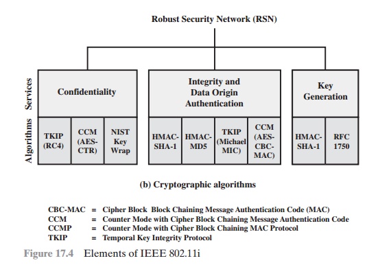
Figure 17.4a indicates the security protocols used to
support these services, while Figure 17.4b lists the cryptographic algorithms
used for these services.
IEEE 802.11i Phases of Operation
The operation of an IEEE 802.11i RSN can be broken down into five distinct phases of operation. The exact nature of the phases will depend
on the configuration and the end points
of the communication. Possibilities include
(see Figure 17.3):
1.
Two
wireless stations in the same BSS
communicating via the access point (AP) for that BSS.
2.
Two wireless
stations (STAs)
in the same ad hoc IBSS communicating directly
with each other.
3.
Two wireless
stations in different BSSs communicating via their respective APs across a distribution system.
4.
A wireless
station communicating with an end station on a wired network via its
AP and the distribution system.
IEEE 802.11i security
is concerned only with secure
communication between the STA and its AP. In case 1 in the preceding list, secure communication is assured if each STA establishes secure communications with the AP. Case 2 is similar, with the
AP functionality residing
in the STA. For case 3, security
is not provided across the distribution system at the level of IEEE 802.11,
but only within
each BSS. End- to-end security
(if required) must be provided
at a higher layer. Similarly, in case 4, security is only provided
between the STA and its AP.
With these considerations in mind, Figure
17.5 depicts the five phases
of oper- ation for an RSN and
maps them to the network components involved. One new component is the
authentication server (AS). The rectangles
indicate the exchange of sequences of MPDUs. The five phases are defined as follows.
•
Discovery: An AP uses messages
called Beacons and Probe Responses to advertise its IEEE 802.11i security policy. The STA uses these to identify an AP for a
WLAN with which it wishes to communicate. The STA
associates with the AP, which it uses to select the cipher suite and authentication mecha- nism when the Beacons
and Probe Responses present a choice.
Authentication: During this phase,
the STA and AS prove their
identities to each other. The AP blocks non-authentication traffic between the STA and AS until
the authentication transaction is successful. The AP does not participate
in the authentication transaction other than forwarding traffic between the STA and
AS.

•
Key generation and distribution: The AP and the STA perform several
opera- tions that cause cryptographic keys to be generated and placed on the AP and
the STA. Frames are exchanged
between the AP and STA only.
•
Protected data transfer: Frames are exchanged
between the STA and the end station through the AP. As denoted by the shading
and the encryption module
icon, secure data transfer occurs between the STA and the AP only; security is not provided end-to-end.
•
Connection
termination: The AP and STA exchange
frames. During this phase,
the secure connection is torn down and the connection is restored to the
original state.
Discovery Phase
We now look in more detail at the RSN phases of operation,
beginning with the discovery phase, which
is illustrated in the upper
portion of Figure
17.6. The purpose of this phase is for an STA and an AP to recognize each other, agree
on a set of secu- rity capabilities, and establish an association for future communication using those security capabilities.
SECURITY CAPABILITIES During this phase, the STA and AP decide on specific
techniques in the following areas:
•
Confidentiality and
MPDU integrity protocols for protecting unicast traffic (traffic only between this STA and AP)
•
Authentication method
•
Cryptography key
management approach
Confidentiality and integrity protocols for protecting multicast/broadcast traf- fic are dictated by the AP, since all STAs in a multicast
group must use the same pro-
tocols and ciphers. The specification of a protocol,
along with the chosen key length
(if variable)
is known as a cipher
suite. The options for
the confidentiality and integrity cipher suite are
•
WEP, with either a 40-bit or 104-bit key, which
allows backward compatibility with older IEEE 802.11
implementations
•
TKIP
•
CCMP
•
Vendor-specific methods
The other negotiable suite is the authentication and key
management (AKM) suite, which
defines (1) the means by which
the AP and STA perform mutual
authentication and (2) the means
for deriving a root key from which
other keys may be
generated. The possible AKM suites are
•
IEEE 802.1X
•
Pre-shared key (no explicit
authentication takes place
and mutual authentica- tion is implied if the STA and AP share a unique secret key)
•
Vendor-specific methods
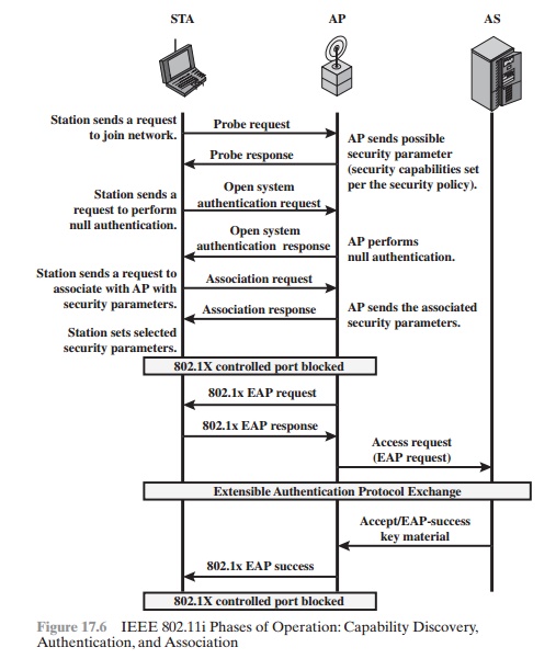
MPDU EXCHANGE The
discovery phase consists of three
exchanges.
•
Network and security capability discovery: During this
exchange, STAs dis-
cover the existence of a network with which to communicate. The AP either periodically broadcasts its security capabilities (not shown in figure), indicated by RSN IE (Robust Security Network Information Element), in
a specific channel through the Beacon
frame; or responds to a station’s Probe Request through a Probe Response frame.
A wireless station may discover available access points and corresponding security capabilities by either passively
mon- itoring the Beacon
frames or actively
probing every channel.
Open
system authentication: The purpose of this frame
sequence, which pro- vides no
security, is simply to
maintain backward
compatibility with the IEEE
802.11 state machine, as implemented in existing IEEE 802.11 hard- ware. In
essence, the two devices (STA and AP) simply exchange identifiers.
•
Association: The purpose of this stage is to agree on a set of security
capabili- ties to be used. The STA then sends an Association Request
frame to the AP. In this frame, the STA specifies one set of matching capabilities (one authenti- cation
and key management suite, one pairwise cipher suite, and one group- key cipher
suite) from among
those advertised by the AP. If there is no match in capabilities between the AP and
the STA, the AP refuses the
Association Request. The STA blocks it too, in case it has
associated with a rogue AP or someone is inserting frames illicitly on its channel. As shown in Figure 17.6,
the IEEE 802.1X controlled ports are blocked,
and no user traffic goes beyond the AP. The concept
of blocked ports is explained
subsequently.
Authentication Phase
As was mentioned, the authentication phase enables mutual authentication between an STA and an authentication
server (AS) located in the DS. Authentication
is designed to allow only authorized
stations to use the network and to provide the STA with assurance that it is communicating with a legitimate network.
IEEE 802.1X ACCESS CONTROL APPROACH IEEE 802.11i makes use of another standard that was designed to provide access control functions for LANs. The standard is IEEE 802.1X,
Port-Based Network Access
Control. The authentication
protocol that is used, the Extensible Authentication Protocol (EAP), is defined
in the IEEE 802.1X standard. IEEE 802.1X uses the terms
supplicant, authenticator,
and authentication server (AS). In
the context of an 802.11 WLAN, the first two terms
correspond to the wireless station and the AP.
The AS is typically a
separate device on the wired side of the network (i.e.,
accessible over the DS) but could also reside directly on the authenticator.
Before a supplicant is authenticated by the AS using an authentication proto- col, the authenticator only passes control
or authentication messages between the supplicant and the AS; the 802.1X
control channel is unblocked, but the 802.11
data channel is blocked. Once a supplicant is authenticated and keys are
provided, the authenticator can forward data from the supplicant, subject to
predefined access control limitations for the supplicant to the network.
Under these circumstances, the data channel is unblocked.
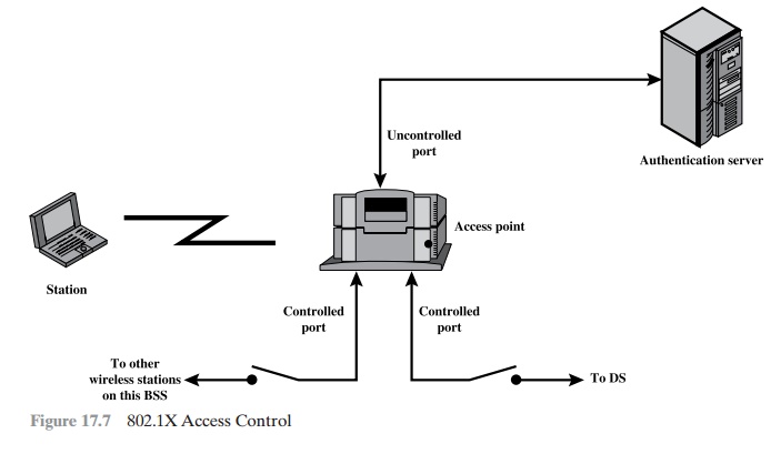
As indicated in Figure 17.7,
802.1X uses the
concepts of controlled and uncon- trolled
ports. Ports are logical entities defined within the authenticator and refer to physical network connections. For a WLAN,
the authenticator (the AP) may have only two physical ports:
one connecting to the DS and one for wireless
communica- tion within its BSS. Each logical
port is mapped to one of these two physical
ports. An uncontrolled port allows the exchange of PDUs between
the supplicant and the
other AS, regardless of the authentication state of the supplicant. A controlled port allows the exchange of PDUs between
a supplicant and other systems
on the LAN only if the current state of the supplicant authorizes such an exchange.
•
The 802.1X framework, with an upper-layer authentication protocol, fits nicely
with a BSS architecture that includes a
number of wireless stations and an AP.
However,
for an IBSS, there
is no AP. For an IBSS,
802.11i provides a more complex solution that, in essence,
involves pairwise authentication between stations on the IBSS.
MPDU EXCHANGE The lower part of
Figure 17.6 shows the MPDU exchange dictated by IEEE 802.11 for the
authentication phase. We can think of authentication phase as consisting of the
following three phases.
•
Connect to AS: The STA sends a request to its AP (the one with which
it has an association) for
connection to the AS. The AP acknowledges this request and sends an access request to the AS.
•
EAP exchange: This
exchange authenticates the STA and
AS to each other. A number of alternative exchanges are possible, as explained subsequently.
•
Secure key delivery: Once authentication is established, the AS generates a master
session key (MSK), also known as the Authentication, Authorization, and Accounting (AAA)
key and sends it to the STA. As explained
subsequently, all the cryptographic
keys needed by the STA for secure communication with its AP are generated from this MSK. IEEE 802.11i
does not prescribe a method for secure delivery of the MSK but relies
on EAP for this. Whatever method is
used, it involves the transmis- sion of an MPDU containing
an encrypted MSK from the AS, via the AP, to
the AS.
EAP EXCHANGE As
mentioned, there are a number of possible EAP exchanges that can be used during
the authentication phase. Typically, the message flow between STA and AP employs the EAP over LAN (EAPOL)
protocol, and the message flow between the AP and AS uses the Remote
Authentication Dial In User
Service (RADIUS) protocol, although other options
are available for both STA-to-
AP and AP-to-AS exchanges. [FRAN07] provides the following summary of the authentication exchange using EAPOL and RADIUS.
1.
The EAP exchange begins with
the AP issuing an EAP-Request/Identity frame to the STA.
2.
The STA replies with
an EAP-Response/Identity frame,
which the AP receives over the uncontrolled port. The
packet is then encapsulated in RADIUS over EAP and passed on to the RADIUS
server as a RADIUS-Access-Request packet.
3.
The AAA server replies
with a RADIUS-Access-Challenge packet, which is
passed on to the STA as an EAP-Request. This request is of
the appropriate authentication type and contains
relevant challenge information.
4.
The STA formulates an EAP-Response
message and sends it to the AS. The response is translated by the AP
into a Radius-Access-Request with the response to the challenge as a data field. Steps 3 and 4 may be repeated
multi- ple times, depending on the EAP method
in use. For TLS tunneling methods,
it is common for authentication to require
10 to 20 round trips.
5.
The AAA server
grants access with a Radius-Access-Accept packet. The AP issues an EAP-Success frame.
(Some protocols require
confirmation of the EAP success
inside the TLS tunnel for authenticity validation.) The controlled port is authorized, and the user may begin
to access the network.
Note from Figure 17.6 that the AP controlled
port is still blocked to general user traffic. Although
the authentication is successful, the ports remain
blocked until the temporal
keys are installed in the STA and AP, which occurs during the 4-Way
Handshake.
Key Management Phase
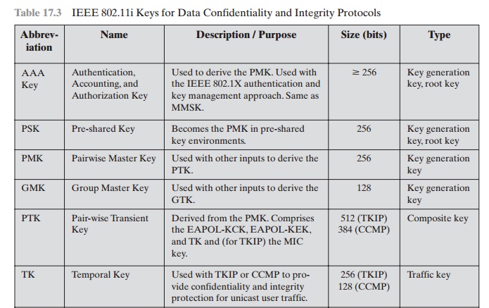
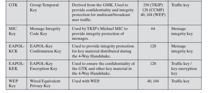
During the key management phase, a variety
of cryptographic keys are generated and distributed to STAs. There are two types of keys: pairwise keys used for commu-
nication between an STA and an AP and group keys used for multicast communica- tion. Figure 17.8,
based on [FRAN07], shows the two
key hierarchies, and Table
17.3 defines the individual keys.
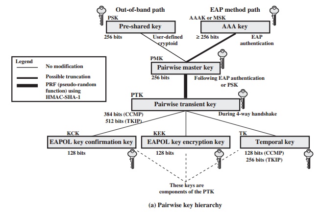
PAIRWISE KEYS Pairwise keys are used for communication between a pair of
devices, typically between an STA and an AP. These keys form a hierarchy
beginning with a master key from which other keys are derived dynamically and
used for a limited period of time.
At the top level of the hierarchy are two possibilities. A pre-shared
key (PSK) is a secret key
shared by the AP and a STA and
installed in some fashion outside the scope of IEEE 802.11i.
The other alternative is the master session key (MSK), also known as the AAAK,
which is generated
using the IEEE 802.1X protocol
dur- ing the authentication phase,
as described previously. The actual method of key generation depends on the details
of the authentication protocol used. In either
case (PSK or MSK), there is a unique key shared by the AP
with each STA with which it
communicates. All the other keys derived from this master key are also unique
between an AP and an STA. Thus, each
STA, at any time, has one set of
keys, as depicted in the hierarchy of Figure 17.8a, while the AP has one set of such keys
for each of its STAs.
The pairwise master key (PMK)
is derived from the master key. If a PSK is
used, then the PSK is used as the PMK; if a MSK is used, then the PMK is derived from the MSK by truncation (if necessary). By the end of the authentication phase, marked by the 802.1x
EAP Success message
(Figure 17.6), both the AP and the STA have
a copy of their shared
PMK.
The PMK is used to generate the pairwise transient key (PTK), which in fact consists of three keys to be used for communication between
an STA and AP after
they have been mutually authenticated. To derive
the PTK, the HMAC-SHA-1 function is applied to the PMK, the MAC addresses of the STA and AP, and nonces generated when needed. Using the STA and AP addresses in the generation of
the PTK provides protection against session hijacking and impersonation; using
nonces provides additional random
keying material.
The three parts of the PTK are as follows.
•
EAP Over LAN (EAPOL) Key
Confirmation Key (EAPOL-KCK): Supports the integrity and data origin
authenticity of STA-to-AP control frames during operational
setup of an RSN. It also performs an
access control function: proof-of-possession of the PMK. An
entity that possesses the PMK is autho-
rized to use the link.
•
EAPOL Key Encryption Key (EAPOL-KEK): Protects the confidentiality of keys and other data during
some RSN association procedures.
•
Temporal Key (TK): Provides the
actual protection for
user traffic.
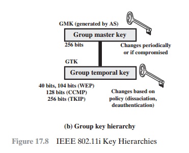
GROUP KEYS Group keys are used for multicast communication in which
one STA sends MPDU’s to multiple
STAs. At the top level of the group key hierarchy
is the group master key (GMK). The GMK is a key-generating key
used with other
inputs to derive the group temporal key (GTK). Unlike the PTK,
which is generated using material from both AP and STA, the GTK is generated by the AP and transmitted to its associated
STAs. Exactly how this GTK is generated
is undefined. IEEE 802.11i, however, requires that its value is computationally indistinguishable from
random. The GTK is distributed
securely using the pairwise keys that are already established. The GTK is changed
every time a device leaves
the network.
PAIRWISE KEY DISTRIBUTION
The upper part of Figure
17.9 shows the MPDU exchange for distributing pairwise keys. This exchange is
known as the 4-way handshake. The
STA and SP use this handshake to confirm the existence of the PMK, verify the
selection of the cipher suite, and derive a fresh PTK for the following data
session. The four parts of the exchange are as follows.
•
AP : STA: Message includes the MAC address
of the AP and a nonce
(Anonce)
•
STA : AP: The STA generates
its own nonce (Snonce) and uses both nonces and both MAC addresses, plus the PMK, to generate a PTK. The STA then sends a message containing its MAC address and Snonce, enabling
the AP to generate the same PTK. This message
includes a message
integrity code (MIC)2 using HMAC-MD5
or HMAC-SHA-1-128. The key used
with the MIC
is KCK.
•
AP : STA: The AP is now able to generate the PTK. The AP then sends a
message to the STA, containing the
same information as in the
first message, but this
time including a MIC.
•
STA : AP: This is merely
an acknowledgment message,
again protected by a
MIC.
GROUP KEY DISTRIBUTION For group key distribution, the
AP generates a GTK and distributes it to each
STA in a multicast group. The two-message exchange with each STA consists of the following:
AP : STA: This message
includes the GTK, encrypted either with RC4 or
with AES. The key used for encryption is KEK. A MIC value
is appended.
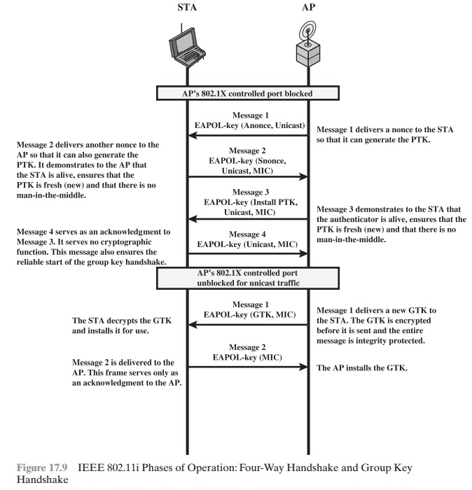
•
STA : AP: The STA acknowledges receipt of the GTK. This
message includes a MIC value.
Protected Data Transfer Phase
IEEE 802.11i defines two schemes for protecting
data transmitted in 802.11 MPDUs: the Temporal Key Integrity Protocol
(TKIP), and the Counter Mode-CBC MAC Protocol (CCMP).
TKIP TKIP is designed to require only software changes to
devices that are implemented with the older wireless LAN security approach
called Wired Equivalent Privacy (WEP). TKIP provides two services:
•
Message integrity: TKIP adds a message
integrity code (MIC) to the 802.11
MAC
frame after the data field.
The MIC is generated by an algorithm, called Michael, that computes
a 64-bit value
using as input
the source and destination
MAC
address values and the Data field, plus key material.
•
Data confidentiality: Data confidentiality is provided by encrypting the MPDU plus MIC value using RC4.
The 256-bit TK (Figure 17.8)
is employed as follows. Two 64-bit
keys are used with the Michael message digest
algorithm to produce a message integrity code. One key is used to protect
STA-to-AP messages, and the other key is used to protect
AP-to-STA messages. The remaining
128 bits are truncated to generate the RC4 key used to encrypt the transmitted data.
For additional protection, a monotonically increasing TKIP sequence counter (TSC) is assigned to each frame.
The TSC serves two purposes. First, the TSC is included with each MPDU and is
protected by the MIC to protect against replay attacks. Second, the TSC is
combined with the session TK to produce a dynamic encryption key that changes
with each transmitted MPDU, thus making cryptanaly- sis more difficult.
CCMP CCMP is intended for newer IEEE 802.11 devices that are
equipped with the hardware to support this scheme. As with TKIP, CCMP provides two services:
•
Message integrity: CCMP uses the
cipher-block-chaining message authentica- tion code (CBC-MAC), described in
Chapter 12.
•
Data confidentiality: CCMP uses the CTR
block cipher mode of operation with AES for encryption. CTR is described
in Chapter 6.
The same 128-bit AES key is used for both integrity
and confidentiality. The scheme
uses a 48-bit packet number to construct
a nonce to prevent
replay attacks.
The IEEE 802.11i Pseudorandom Function
At a number of places in the
IEEE 802.11i scheme, a pseudorandom
function (PRF) is used. For example, it is used to generate
nonces, to expand pairwise keys, and to generate the GTK. Best
security practice dictates that different pseudoran- dom number streams be used for these different purposes. However, for implemen-
tation efficiency, we would like to rely on a
single pseudorandom number generator function.
The PRF is built on the use of HMAC-SHA-1 to generate a pseudorandom bit stream. Recall that HMAC-SHA-1 takes
a message (block of data) and a key of length
at least 160 bits and produces a 160-bit hash value. SHA-1
has the property that the change of a single
bit of the input produces
a new hash value with no appar- ent connection to the preceding hash value. This property is the basis for pseudorandom number generation.
The IEEE
802.11i PRF takes four parameters as
input and produces the desired number
of random bits. The function
is of the form PRF(K, A, B, Len), where
K = a secret key
A = a text string specific to the application (e.g., nonce generation or pair- wise key
expansion)
B = some data specific to each case
Len
= desired number of pseudorandom bits
For example, for the pairwise transient key for CCMP:
PTK
= PRF(PMK, "Pairwise key expansion", min(AP– Addr, STA–Addr)|| max(AP–Addr, STA–Addr) | min
(Anonce, Snonce) | max(Anonce, Snonce),
384)
So, in this case, the parameters are
K = PMK
A = the text string "Pairwise key expansion"
B = a sequence of bytes formed by concatenating the two MAC addresses and the two nonces
Len
= 384 bits
Similarly, a nonce is generated by
Nonce = PRF(Random Number, "Init Counter", MAC | Time, 256)
where Time is
a measure of the network time known to the nonce generator.
The group temporal key is generated by
GTK = PRF(GMK, "Group key expansion", MAC | Gnonce, 256)
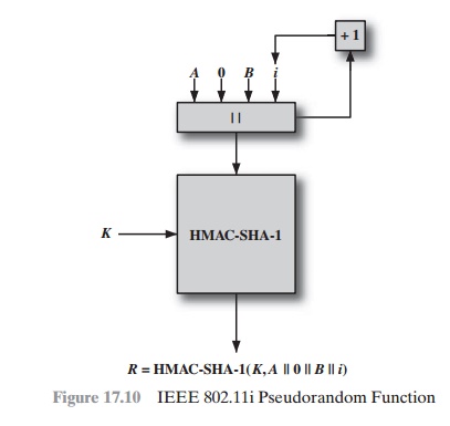
Figure 17.10 illustrates
the function PRF(K, A, B, Len). The parameter K serves as the key input to HMAC. The message input consists of four items concate-
nated together: the parameter
A, a byte with value 0, the parameter
B, and a counter i.
The
counter is initialized to 0. The HMAC algorithm
is run once, producing a 160-bit hash value. If more bits are required, HMAC
is run again with the same inputs, except that i is incremented each time until the
necessary number of bits is gener- ated. We can express
the logic as
PRF(K, A, B,
Len)
R ‹- null string
for i ‹- 0 to ((Len + 159)/160 – 1) do
R ‹- R | HMAC–SHA–1(K, A ||0 |B |i)
Return Truncate–to–Len(R, Len)
Related Topics