Chapter: Cryptography and Network Security Principles and Practice : Network and Internet Security : Wireless Network Security
IEEE 802.11 Wireless LAN Overview: Wi-Fi Alliance, Protocol Architecture, Network Components
IEEE 802.11
WIRELESS LAN OVERVIEW
IEEE 802 is a committee that has developed standards for a
wide range of local area networks (LANs). In 1990, the IEEE 802 Committee
formed a new working group, IEEE 802.11, with a charter to develop a protocol
and transmission specifications for
wireless LANs (WLANs). Since that time, the demand for WLANs at different
frequencies and data rates has exploded. Keeping
pace with this demand, the IEEE
working
group has issued an ever-expanding list of
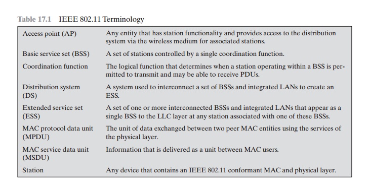
standards. Table 17.1 briefly defines
key terms used in the IEEE 802.11 standard.
The Wi-Fi Alliance
The first 802.11 standard to gain broad industry acceptance was 802.11b. Although 802.11b products are all based on
the same standard, there is always a concern
whether products from different vendors
will successfully interoperate. To meet this
concern, the Wireless Ethernet Compatibility Alliance (WECA), an industry con-
sortium, was formed in 1999. This organization, subsequently renamed the Wi-Fi (Wireless Fidelity) Alliance, created a test
suite to certify interoperability for 802.11b
products. The term used
for certified 802.11b
products is Wi-Fi. Wi-Fi certi- fication has been extended
to 802.11g products,. The Wi-Fi Alliance has also devel- oped a certification process
for 802.11a products,
called Wi-Fi5. The Wi-Fi Alliance
is concerned with a range
of market areas
for WLANs, including enterprise, home,
and hot spots.
More recently, the Wi-Fi Alliance has
developed certification procedures for IEEE 802.11 security standards, referred
to as Wi-Fi Protected Access (WPA). The most recent version of WPA, known as
WPA2, incorporates all of the features of the IEEE 802.11i WLAN security specification.

IEEE 802 Protocol Architecture
Before proceeding, we need to briefly preview
the IEEE 802 protocol architecture. IEEE 802.11 standards are defined within
the structure of a layered
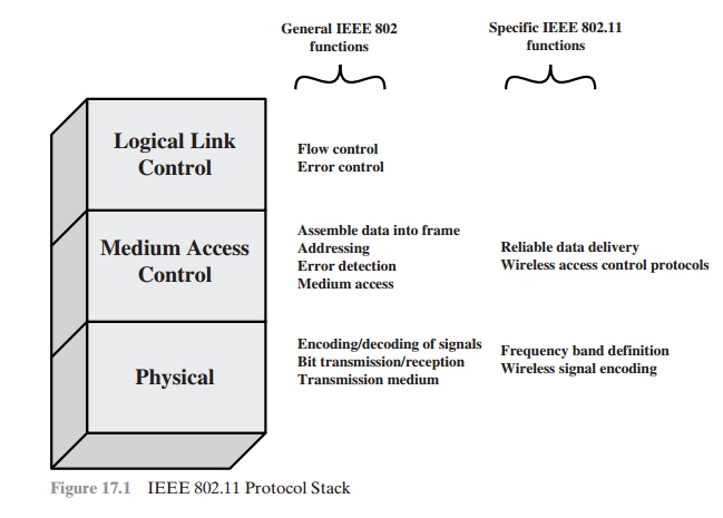
set of protocols. This structure, used for all IEEE 802 standards, is illustrated in Figure 17.1.
PHYSICAL LAYER The
lowest
layer of the IEEE 802 reference model is the physical layer, which includes such functions as encoding/decoding of
signals and bit transmission/reception. In addition, the physical layer
includes a specification of the transmission
medium. In the case of IEEE 802.11, the physical layer also defines frequency bands and antenna
characteristics.
MEDIA ACCESS CONTROL
All LANs consist of
collections of devices that share the network’s
transmission capacity. Some means of
controlling access to the transmission
medium is needed to provide an orderly and efficient use
of that capacity. This is the function
of a media access control
(MAC) layer. The MAC layer receives data from a higher-layer protocol, typically the Logical
Link Control (LLC) layer, in the form of a block of data known
as the MAC service data unit (MSDU). In general, the MAC layer performs
the following functions:
•
On transmission, assemble data into a frame,
known as a MAC protocol
data unit (MPDU) with address
and error-detection fields.
•
On reception,
disassemble frame, and perform address recognition and error detection.
•
Govern access
to the LAN transmission medium.


The exact format
of the MPDU differs somewhat
for the various
MAC proto- cols in use. In general,
all of the MPDUs have a format
similar to that of Figure
17.2. The fields of this frame are as follows.
•
MAC Control: This field
contains any protocol
control information needed
for the functioning of the MAC protocol.
For example, a priority level could
be indicated here.
•
Destination MAC Address: The destination physical address
on the LAN for this MPDU.
•
Source MAC Address: The source physical
address on the LAN for this MPDU.
•
MAC Service Data
Unit: The data from
the next higher
layer.
•
CRC: The cyclic redundancy
check field; also known as the Frame
Check Sequence (FCS) field. This is an
error-detecting code, such as that which is used in other data-link control protocols. The CRC is calculated based
on the bits in the entire MPDU. The sender calculates the CRC and
adds it to the frame. The receiver performs the same calculation on the
incoming MPDU and compares that calculation to the CRC field in that incoming
MPDU. If the two values don’t match, then one or more bits have been altered
in transit.
The fields preceding
the MSDU field are referred
to as the MAC header, and the field following the MSDU field
is referred to as the MAC trailer. The header and trailer contain control information
that accompany the data field and that are used by the MAC protocol.
LOGICAL LINK
CONTROL In
most data-link control protocols, the data-link protocol entity is responsible not only for detecting errors using the CRC, but for recovering from those errors by retransmitting
damaged frames. In the LAN protocol architecture, these two functions
are split between the MAC and LLC
layers. The MAC layer is responsible
for detecting errors and discarding any frames that contain errors. The LLC layer
optionally keeps track of which frames have been successfully received and retransmits unsuccessful frames.
IEEE 802.11 Network Components and Architectural Model
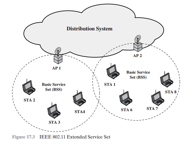
Figure 17.3 illustrates the model developed by the 802.11
working group.
The smallest building block of a wireless LAN is a basic service set
(BSS), which consists of wireless stations executing
the same MAC protocol and competing
for access to the same shared wireless medium. A BSS may be isolated, or it may
connect to a backbone

distribution system (DS) through an access point (AP). The AP functions as a bridge
and a relay point. In a BSS, client
stations do not communicate directly with one another. Rather, if one station
in the BSS wants to communicate with another station in the same BSS, the MAC frame is first sent from the originating station
to the AP and then from the AP to the destination station.
Similarly, a MAC frame from a sta- tion in the BSS to a remote station
is sent from the local station to the AP and then relayed by the AP over the
DS on its way to the destination station.The BSS generally corresponds to what is referred to as a cell in the literature. The DS can be a switch,
a wired network, or a wireless network.
When all the stations in the BSS are mobile
stations that communicate directly with one another
(not using an AP), the BSS is called an independent BSS (IBSS). An IBSS is typically an ad hoc network. In an IBSS, the stations all communicate directly,
and no AP is involved.
A simple configuration is shown in Figure
17.3, in which each station belongs to a single BSS; that is, each station is within wireless range
only of other stations within the same BSS.
It is also possible for two BSSs to overlap geographically, so that a
single station could participate in more than one BSS. Furthermore, the asso- ciation between a station and a BSS
is dynamic. Stations may turn off, come
within range, and go out of range.
An extended service
set (ESS) consists of two or more basic service sets interconnected by a distribution system.
The extended service set appears as a single logical LAN to the logical link control (LLC)
level.
IEEE 802.11 Services
IEEE 802.11 defines
nine services that need to be provided
by the wireless LAN to achieve functionality equivalent to that which is inherent
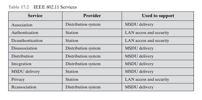
to wired LANs. Table 17.2 lists the services and
indicates two ways
of categorizing them.
1.
The service provider can be
either the station or the DS. Station
services are implemented in every
802.11 station, including AP stations. Distribution ser- vices are provided
between BSSs; these
services may be implemented in an AP or
in another special-purpose device attached to the distribution system.
2.
Three of the services
are used to control IEEE 802.11 LAN access and confi-
dentiality. Six of the services
are used to support delivery
of MSDUs between stations. If the MSDU is too large to be transmitted in a single
MPDU, it may be fragmented and transmitted in a series
of MPDUs.
Following
the IEEE 802.11 document, we next discuss
the services in an order designed to clarify the operation of an IEEE 802.11 ESS network. MSDU delivery, which is the basic service,
already has been mentioned. Services
related to security are introduced in Section
17.2.
DISTRIBUTION OF MESSAGES WITHIN A DS
The two services involved with the distribution of messages within
a DS are distribution and integration. Distribution is
the primary service used by stations to exchange MPDUs when the MPDUs must
traverse the DS to get from a station in one BSS to a station in another BSS. For
example, suppose a frame is to be sent from station 2 (STA 2) to station 7 (STA 7) in Figure 17.3. The frame is sent from STA 2 to AP 1, which is the AP for this BSS. The AP gives the frame to the DS, which has the job of directing the
frame to the AP associated with STA 7 in the target BSS. AP 2 receives
the frame and forwards it to
STA 7. How the message is
transported through the DS is beyond the scope of the IEEE 802.11 standard.
If the two stations that are communicating
are within the same BSS, then the
distribution service logically goes through the single AP of that BSS.
Table 17.2
IEEE 802.11 Services

The integration service enables transfer
of data between a station
on an IEEE
LAN and a station on
an integrated IEEE 802.x LAN. The term integrated refers to a wired LAN that is physically connected to
the DS and whose stations may be logically connected to an IEEE 802.11
LAN via the integration service.
The integration service
takes care of any address
translation and media conversion logic required for the exchange of data.
ASSOCIATION-RELATED SERVICES The primary purpose of the MAC
layer is to transfer MSDUs between
MAC entities; this purpose
is fulfilled by the distribution
service. For that service to function, it requires
information about stations within
the ESS that is provided
by the association-related services. Before the distribution
service can deliver data
to or accept data from a station, that
station must be associated.
Before looking at the concept of association, we need to describe the concept
of mobility. The standard defines three transition types, based on mobility:
•
No transition: A station
of this type is either
stationary or moves
only within the direct
communication range of the communicating stations of a single BSS.
•
BSS transition: This is defined as
a station movement from one BSS to another BSS within the same ESS. In this case, delivery
of data to the station requires that the addressing
capability be able to recognize the new location of the station.
•
ESS transition: This is defined as a station
movement from a BSS in one ESS to
a BSS within another ESS. This case is supported only in the sense that the
station can move. Maintenance of upper-layer
connections supported by
802.11 cannot be guaranteed. In fact,
disruption of service is likely to occur.
To deliver a
message within a DS, the distribution
service needs to know where the destination
station is located. Specifically,
the DS needs to know the identity
of the AP to which the message should be delivered in order for that mes- sage
to reach the destination
station. To meet this requirement, a station must
maintain an association with the AP within its current BSS. Three
services relate to this requirement:
•
Association: Establishes an
initial association between a station and an AP.
Before a station
can transmit or receive frames on a wireless LAN, its identity
and address must be known.
For this purpose, a station must establish an asso-
ciation with an AP within a particular BSS. The AP can then communicate this information to other APs within the
ESS to facilitate routing and delivery of addressed frames.
•
Reassociation: Enables an established association to be transferred from one
AP to another, allowing a mobile station to move from one BSS to another.
•
Disassociation: A notification from either a station or an AP that an existing
association is terminated. A station should
give this notification before leaving an
ESS or shutting down. However, the MAC management
facility protects itself against stations
that disappear without
notification.
Related Topics