Chapter: Mechanical : Manufacturing Technology : Shaper, Milling and Gear Cutting Machines
Gear milling and Gear hobbing
Gear
Gears can be manufactured by most
of manufacturing processes discussed so far (casting, forging, extrusion,
powder metallurgy, blanking). But as a rule, machining is applied to achieve
the final dimensions, shape and surface finish in the gear. The initial
operations that produce a semi finishing part ready for gear machining as
referred to as blanking operations; the starting product in gear machining is
called a gear blank.
Two principal methods of gear manufacturing include
Gear forming, and Gear generation.
Each method includes a number of
machining processes, the major of them included in this section.
Gear forming
In gear form cutting, the cutting
edge of the cutting tool has a shape identical with the shape of the space
between the gear teeth.
Two
machining operations, milling and broaching can be employed to form cut gear
teeth

Gear milling
In form milling, the cutter
called a form cutter travels axially along the length of the gear tooth at the
appropriate depth to produce the gear tooth. After each tooth is cut, the
cutter is withdrawn, the gear blank is rotated (indexed), and the cutter
proceeds to cut another tooth. The process continues until all teeth are cut.
Each cutter is designed to cut a
range of tooth numbers. The precision of the form-cut tooth profile depends on
the accuracy of the cutter and the machine and its stiffness. In form milling,
indexing of the gear blank is required to cut all the teeth. Indexing is the
process of evenly dividing the circumference of a gear blank into equally spaced
divisions. The index head of the indexing fixture is used for this purpose.
The index
fixture consists of an index head (also dividing head, gear cutting attachment)
and footstock, which is similar to the tailstock of a lathe. The index head and
footstock attach to the worktable of the milling machine. An index plate
containing graduations is used to control the rotation of the index head
spindle. Gear blanks are held between centers by the index head spindle and
footstock. Workpieces may also be held in a chuck mounted to the index head
spindle or may be fitted directly into the taper spindle recess of some
indexing fixtures.
Gear
hobbing

Gear hobbing is a machining
process in which gear teeth are progressively generated by a series of cuts
with a helical cutting tool (hob). All motions in hobbing are rotary, and the
hob and gear blank rotate continuously as in two gears meshing until all teeth
are cut when bobbing a spur gear, the angle between the hob and gear blank axes
is 90° minus the lead angle at the hob threads. For helical gears, the hob is
set so that the helix angle of the hob is parallel with the tooth direction of
the gear being cut. Additional movement along the tooth length is necessary in
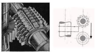
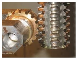
order to cut the whole tooth length: The action of the hobbing machine (also
gear hobber) is shown in the figures. The cutting of a gear by means of a hob
is a continuous operation. The hob and the gear blank are connected by a proper
gearing so that they rotate in mesh. To start cutting a gear, the rotating hob
is fed inward until the proper setting for tooth depth is achieved, then
cutting continues until the entire gear is finished.
The gear hob is a formed tooth
milling cutter with helical teeth arranged like the thread on a screw. These
teeth are fluted to produce the required cutting edges.
Related Topics