Chapter: Mechanical : Dynamics of Machines : Forced Vibration
Forced Vibration
FORCED VIBRATION
1 INTRODUCTION:
When a system is subjected continuously to time
varying disturbances, the vibrations resulting under the presence of the
external disturbance are referred to as forced vibrations.
Forced
vibration is when an alternating force or motion is applied to a mechanical system. Examples of this
type of vibration include a shaking washing machine due to an imbalance,
transportation vibration (caused by truck engine, springs, road, etc), or the
vibration of a building during an earthquake. In forced vibration the frequency
of the vibration is the frequency of the force or motion applied, with order of
magnitude being dependent on the actual mechanical system.
When a vehicle moves on a rough road, it is
continuously subjected to road undulations causing the system to vibrate
(pitch, bounce, roll etc). Thus the automobile is said to undergo forced
vibrations. Similarly whenever the engine is turned on, there is a resultant
residual unbalance force that is transmitted to the chassis of the vehicle
through the engine mounts, causing again forced vibrations of the vehicle on
its chassis. A building when subjected to time varying ground motion
(earthquake) or wind loads, undergoes forced vibrations. Thus most of the
practical examples of vibrations are indeed forced vibrations.
2 CAUSES RESONANCE:
Resonance
is simple to understand
if you view the spring and mass
as energy storage
elements – with the
mass storing kinetic energy and the spring storing potential energy. As
discussed earlier, when the mass and spring have no force acting on them they
transfer energy back and forth at a rate equal to the natural frequency. In
other words, if energy is to be efficiently pumped into both the mass and
spring the energy source needs to feed the energy in at a rate equal to the
natural frequency. Applying a force to the mass and spring is similar to
pushing a child on swing, you need to push at the correct moment if you want
the swing to get higher and higher. As in the case of the swing, the force
applied does not necessarily have to be high to get large motions; the pushes
just need to keep adding energy into the system.
The
damper, instead of storing energy, dissipates energy. Since the damping force
is proportional to the velocity, the more the motion, the more the damper
dissipates the energy. Therefore a point will come when the energy dissipated
by the damper will equal the energy being fed in by the force. At this point,
the system has reached its maximum amplitude and will continue to vibrate at
this level as long as the force applied stays the same. If no damping exists,
there is nothing to dissipate the energy and therefore theoretically the motion
will continue to grow on into infinity.
3 FORCED VIBRATION OF A SINGLE
DEGREE-OF-FREEDOM SYSTEM:
We saw that when a system is given an initial input
of energy, either in the form of an initial displacement or an initial
velocity, and then released it will, under the right conditions, vibrate
freely. If there is damping in the system, then the oscillations die away. If a
system is given a continuous input of energy in the form of a continuously
applied force or a continuously applied displacement, then the consequent
vibration is called forced vibration. The energy input can overcome that
dissipated by damping mechanisms and the oscillations are sustained.
We will consider two types of forced vibration. The
first is where the ground to which the system is attached is itself undergoing
a periodic displacement, such as the vibration of a building in an earthquake.
The second is where a periodic force is applied to the mass, or object
performing the motion; an example might be the forces exerted on the body of a
car by the forces produced in the engine. The simplest form of periodic force
or displacement is sinusoidal, so we will begin by considering forced vibration
due to sinusoidal motion of the ground. In all real systems, energy will be
dissipated, i.e. the system will be damped, but often the damping is very
small. So let us first analyze systems in which there is no damping.
4 STEADY STATE RESPONSE DUE TO
HARMONIC OSCILLATION:
Consider
a spring-mass-damper system as shown in figure 4.1. The equation of motion of
this system subjected to a harmonic force Fsin(wt) can be given by

where, m , k
and c are the mass, spring stiffness
and damping coefficient of the system, F
is the amplitude of the force, w is
the excitation frequency or driving frequency.
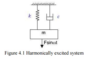
Figure
4.1 Harmonically excited system
Figure
4.2: Force polygon
The
steady state response of the system can be determined by solving equation(4.1)
in many different ways. Here a simpler graphical method is used which will give
physical understanding to this dynamic problem. From solution of differential
equations it is known that the steady state solution (particular integral) will
be of the form
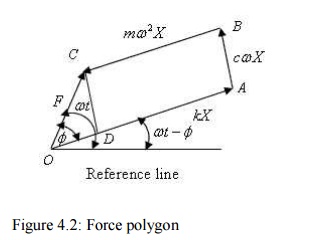
As each
term of equation (4.1) represents a forcing term viz., first, second and third
terms, represent the inertia force, spring force, and the damping forces. The
term in the right hand side of equation (4.1) is the applied force. One may
draw a close polygon as shown in figure 4.2 considering the equilibrium of the
system under the action of these forces. Considering a reference line these
forces can be presented as follows.

From
equation (1), the resultant of the spring force, damping force and the inertia
force will be the applied force, which is clearly shown in figure 4.2.
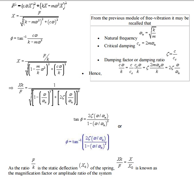
It may be
noted that till now, we don't know about the magnitude of X and $ which can be easily computed from Figure 2.
Drawing a line CD parallel to AB, from the triangle OCD of Figure 2,
5 FORCED VIBRATION WITH DAMPING:
In this
section we will see the behaviour of the spring mass damper model when we add a
harmonic force in the form below. A force of this type could, for example, be
generated by a rotating imbalance.

If we
again sum the forces on the mass we get the following ordinary differential
equation:

The
steady state solution of this problem can be written as:

The
result states that the mass will oscillate at the same frequency, f, of the
applied force, but with a phase shift φ.
The
amplitude of the vibration ―X‖ is defined by the following formula.

Where
―r‖ is defined as the ratio of the harmonic force frequency over the undamped natural
frequency of the mass–spring–damper
model.

The phase
shift , φ, is
defined by the following formula.
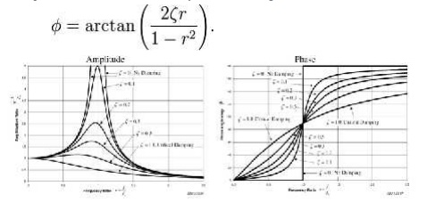
The plot
of these functions, called "the frequency response of the system",
presents one of the most important features in forced vibration. In a lightly
damped system when the forcing frequency nears the natural frequency ( r ~= 1)
the amplitude of the vibration can get extremely high. This phenomenon is
called resonance (subsequently the natural frequency of a system is often
referred to as the resonant frequency). In rotor bearing systems any rotational
speed that excites a resonant frequency is referred to as a critical speed.
If resonance
occurs in a
mechanical system it
can be very
harmful – leading to eventual failure of the system.
Consequently, one of the major reasons for vibration analysis is to predict
when this type of resonance may occur and then to determine what steps to take
to prevent it from occurring. As the amplitude plot shows, adding damping can
significantly reduce the magnitude of the vibration. Also, the magnitude can be
reduced if the natural frequency can be shifted away from the forcing frequency
by changing the stiffness or mass of the system. If the system cannot
be changed, perhaps
the forcing frequency can
be shifted (for
example, changing the speed of the machine generating the force).
The
following are some other points in regards to the forced vibration shown in the
frequency response plots.
At a
given frequency ratio, the amplitude of the vibration, X, is directly
proportional to the amplitude of the force F0 (e.g. if you double
the force, the vibration doubles)
With
little or no damping, the vibration is in phase with the forcing frequency when
the frequency ratio r < 1 and 180 degrees out of phase when the frequency
ratio r > 1

by the
mass increases with the frequency. Since the deflection seen in the spring, X,
is reduced in this region, the force transmitted by the spring (F = kx) to the
base is reduced. Therefore the mass–spring–damper≫ system is isolating the harmonic
force from the mounting base – referred to as vibration isolation. Interestingly,
more damping actually reduces the effects of vibration isolation when r 1
because the damping force (F = cv) is also transmitted to the base.
6 ROTATING UNBALANCE FORCED VIBRATION:
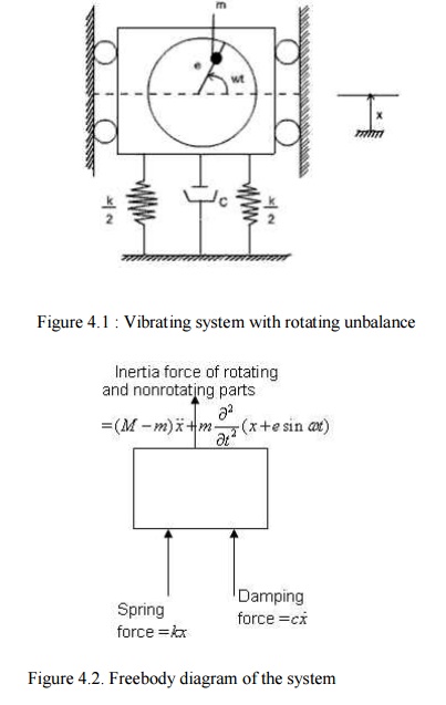
One may
find many rotating systems in industrial applications. The unbalanced force in
such a system can be represented by a mass m
with eccentricity e , which is
rotating with angular velocity as shown in Figure 4.1.
Figure
4.1 : Vibrating system with rotating unbalance
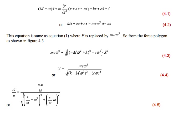
Figure
4.2. Freebody diagram of the system
Let x be
the displacement of the nonrotating mass (M-m) from the static equilibrium
position, then the displacement of the rotating mass m is x+esinwt
From the
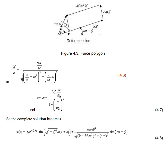
freebody diagram of the system shown in figure 4.2, the equation of motion is
7 VIBRATION ISOLATION AND
TRANSMISSIBILITY:
When a
machine is operating, it is subjected to several time varying forces because of
which it tends to exhibit vibrations. In the process, some of these forces are
transmitted to the foundation – which
could undermine the life of the foundation and also affect the operation of any
other machine on the same foundation. Hence it is of interest to minimize this
force transmission. Similarly when a system is subjected to ground motion, part
of the ground motion is transmitted to the system as we just discussed e.g., an
automobile going on an uneven road; an instrument mounted on the vibrating
surface of an aircraft etc. In these cases, we wish to minimize the motion
transmitted from the ground to the system. Such considerations are used in the
design of machine foundations and in order to understand some of the basic
issues involved, we will study this problem based on the single d.o.f model
discussed so far.
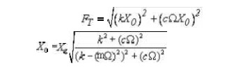
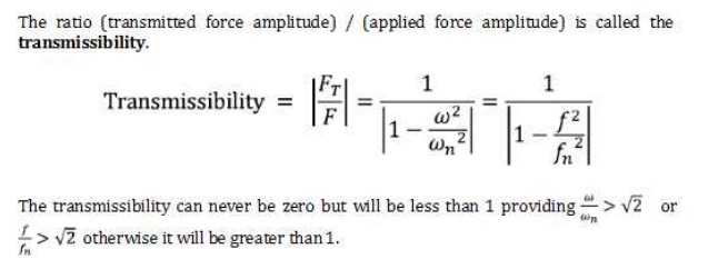
we get the expression for force transmitted to the base as follows:
Vibration Isolators:
Consider
a vibrating machine; bolted to a rigid floor (Figure 2a).The force transmitted
to the floor is equal to the force generated in the machine. The transmitted
force can be decreased by adding a suspension and damping elements (often
called vibration isolators) Figure 2b , or by adding what is called an inertia
block, a large mass (usually a block of cast concrete), directly attached to
the machine (Figure 2c).Another option is to add an additional level of mass
(sometimes called a seismic mass, again a block of cast concrete) and
suspension (Figure 2d).
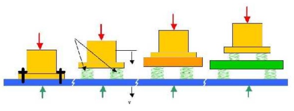
Figure
2.Vibrat ion iso lat ion systems: a) Machine bo lted to a rigid foundation
b)
Supported o n iso lat io n springs, rigid fo u ndat io n c) machine attached to
an inertial block. d) Supported on isolation springs, non -rigid foundation
(such as a floor); or machine on isolation springs, seismic mass and seco nd
level of isolator springs
When oscillatory forces arise unavoidably in
machines it is usually desired to prevent these forces from being transmitted
to the surroundings. For example, some unbalanced forces are inevitable in a
car engine, and it is uncomfortable if these are wholly transmitted to the car
body. The usual solution is to mount the source of vibration on sprung
supports. Vibration isolation is measured in terms of the motion or force
transmitted to the foundation. The lesser the force or motion transmitted the
greater the vibration isolation
Suppose that the foundation is effectively rigid
and that only one direction of movement is effectively excited so that the
system can be treated as having only one degree of freedom.
8 RESPONSE WITHOUT DAMPING:
The amplitude of the force transmitted to the
foundations is Where k is the Stiffness of the support
and x(t)
is the displacement of the mass m.
The
governing equation can be determined by considering that the total forcing on
the machine is equal to its mass multiplied by its acceleration (Newton’s
second law)
Related Topics