Chapter: Pharmaceutical Drug Analysis: Flame Spectroscopy
Flame Spectroscopy: Instrumentation
INSTRUMENTATION
There are two
types of Flame Photometers that are
used invariably in Flame Emission
Spectroscopy (FES), namely :
(a) Simple
Flame Photometer, and
(b) Internal
Standard Flame Photometer.
These two
typical instruments shall be discussed briefly here highlighting their various
components and procedural details.
1. SIMPLE FLAME PHOTOMETER
The line-sketch of a simple flame photometer is shown in
Figure 25.2.
In general, Flame Photometers are designed and intended
mainly for carrying out the assay of elements like : Sodium, Potassium,
Calcium, and Lithium that possess the ability to give out an easily excited
flame spectrum having sufficient intensity for rapid detection by a photocell.
Procedure :
The compressed and filtered
air (A) is first introduced into a Nebulizer (E) which creates a negative pressure (suction) enabling
the liquid sample (C) to gain entry into the atomizer (E). Thus, it mixes with
the stream of air as a fine droplet (mist) which goes into the burner (G). The
fuel gas (D) intro-duced into the mixing chambers (F) at a given pressure gets
in touch with the air and the mixture is ignited. Consequently, the radiation
from the resulting flame (H) is made to pass through a convex lens (I) and
ultimately through an optical filter (J) that allows specifically the radiation
characteristic of the element under examination to pass through the photocell
(K). Finally, the output from the photocell is adequately amplified (L) and
subsequently measured on an appropriate sensitive digital-read-out device.
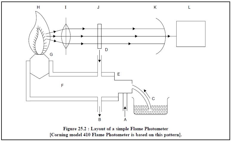
A = Inlet for compressed Air,
B = Drain outlet (to maintain constant pressure head in
the mixing Chamber),
C = Liquid sample (sucked into the Nebulizer),
D = Inlet for Fuel-Gas to the Laminar-Flow-Burner,
E = Nebulizer to atomize the liquid sample,
F = Mixing Chamber for Fuel
Gas, Compressed Air, and Atomized
Liquid Sample,
G = Burner,
H = Flame,
I = Convex lens,
K = Optical filter to transmit only a strong-line of the
element, and
L = Amplifier to amplify the feeble electrical impulse
and a built-in direct read-out device.
2. INTERNAL STANDARD FLAME PHOTOMETER
The layout of an internal standard flame photometer is
illustrated in Figure 25.3.
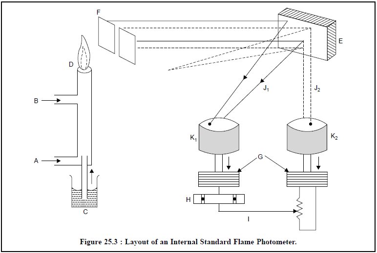
A = Inlet for compressed air,
B = Inlet for Acetylene (Fuel-Gas),
C = Liquid sample sucked in by an atomizer,
D = Flame,
E = Mirror,
F = An optical filter to allow the transmission of only
one strong-line of the element, G
G= Amplifier to amplify the weak electrical current,
H = A Null detector to record the intensity of the element under study and the internal-stand-ard (Lithium),
I = A calibrated potentiometer,
J1 = Lines due to the ‘sample’
J2 = Lines due to the Internal Standard
‘Lithium’, and
K1 & K2 = Photocells to convert
light-energy to electrical impulse.
The use of an internal standard flame photometer not only
eliminates the visible effects of momentary fluctuations in the flame
characteristics produced by variations in either the oxidant or under full
pressures, but also the errors caused due to differences in surface tension and
in viscosity are minimised to a great extent.
Procedure :
In this particular instance
‘Lithium’ is employed as an internal standard and an equal concentration is added simultaneously to the sample and the
standard solutions. The sample (C) solution having the internal standard
(Lithium) is sucked in by an atomizer and a fine spray is thereby introduced
into the flame (D). The radiation thus emitted is subsequently passed through a
filter (F) and then collected by a mirror (E). The emitted radiation reflected
from the mirror is split up into two parts : the first part is caused due to
the internal standard (Lithium), whereas the second part arises due to the
element under examination. Both these lines J1 and J2 are
passed through the respective photocells K1 and K2
whereby the light energy is transformed into the electrical impulses. These
electrical impulses are usually very weak and feeble and hence, they are duly
amplified by a suitable amplifier (G) individually and are subsequently
introduced into the common detecting device (H) i.e., a ‘Null detector’-so
as to enable it to record the intensity of the element under investigation and
also the internal standard (Lithium) accurately using a calibrated
potentiometer (I).
In short, an internal-standard
flame photometer provides a direct and simultaneous result with respect to
the ratio of intensities.
Related Topics