Chapter: Mechanical : Finite Element Analysis : Finite Element Formulation of Boundary Value Problems
Finite Element Formulation of Boundary Value Problems
FINITE ELEMENT FORMULATION OF BOUNDARY VALUE
PROBLEMS
INTRODUCTION
The finite element method constitutes a general
tool for the numerical solution of partial differential equations in
engineering and applied science.
The finite element method (FEM), or finite element
analysis (FEA), is based on the idea of building a complicated object with
simple blocks, or, dividing a complicated object into small and manageable
pieces. Application of this simple idea can be found everywhere in everyday life
as well as in engineering.
Examples:
Lego
(kids’play)
Buildings
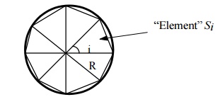
Approximation
of the area of a circle:
Why
Finite Element Method?
·
Design analysis:
hand calculations, experiments, and computer simulations
·
FEM/FEA is the most widely applied computer
simulation method in engineering
·
Closelyintegrated with CAD/CAM applications
1.A Brief History of the FEM
·
1943 --- Courant (variational method)
·
1956 --- Turner, clough, martin and top(stiffness)
·
1960 --- Clough (finite element plan problems)
·
1970 --- Applications on mainframe computer
·
1980 --- Microcomputers, pre and post processors
·
1990 --- Analysis of large structural systems
2.General Methods of the Finite
Element Analysis
2. Force
Method – Internal
forces are considered as the unknowns of the problem.
3.
Displacement or stiffness method –
Displacements of the nodes are considered as the unknowns of the problem.
3.General Steps of the Finite
Element Analysis
·
Discretization of structure
·
Numbering of Nodes and Elements
·
Selection of Displacement function or
interpolation function
·
Define the material behavior by using Strain –
Displacement and Stress – Strain relationships
·
Derivation of element stiffness matrix and
equations
·
Assemble the element equations to obtain the
global or total equations
·
Applying boundary conditions
·
Solution for the unknown displacements computation
of the element strains and stresses from the nodal displacements
·
Interpret the results (post processing).
4.Objectives of This FEM
·
Understand the fundamental ideas of the FEM
·
Know the behavior and usage of each type of
elements covered in this course
·
Be able to prepare a suitable FE model for given
problems
·
Can interpret and evaluate the quality of the
results (know the physics of the problems)
·
Be aware of the limitations of the FEM (don’t misuse
the
·
FEM - a numerical tool)
5.Applications of FEM in
Engineering
·
Mechanical/Aerospace/Civil/Automobile Engineering
Structure analysis (static/dynamic, linear/nonlinear) Thermal/fluid flows
·
Electromagnetics
·
Geomechanics
·
Biomechanics
WEIGHTED RESIDUAL METHOD
It is a powerful approximate procedure applicable
to several problems. For non –structural problems, the method
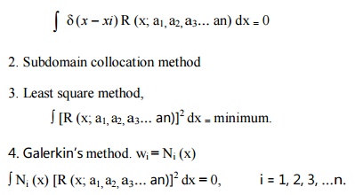
of weighted residuals becomes very useful. It has many types. The popular four
methods are,
1. Point
collocation method,
Residuals
are set to zero at n different locations Xi, and the weighting
function wi is denoted as d(x - xi).
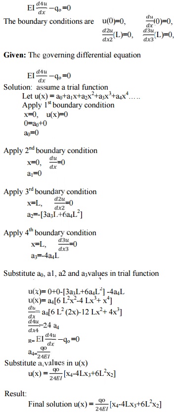
roblem I
Find the
solution for the following differential equation.
Problem 2
The
differential equation of a physical phenomenon is given by
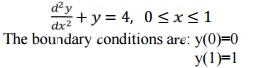
Obtain
one term approximate solution by using galerkin method Solution:
Here
the boundary conditions are not homogeneous so we assume a trial function as,
y=a1x(x-1)+x
first
we have to verify whether the trial function satisfies the boundary condition
or not y=a1x(x-1)+x
when x=0, y=0 x=1, y=1
Resuldual
R:
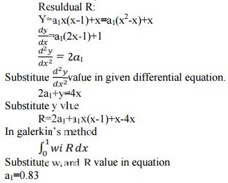
So
one of the approximate solution is,
y=
0.83x(x-1)+x = 0.83x2-0.83x+x
y=0.83
x2+0.17x
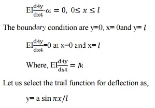
Problem 3
Find
the deflection at the center of a simply supported beam of span length l
subjected to uniform distributed load throughout its length as shown using (a)
point collection method (b) Sub-
domain
method (c)least squared and (d)
galerkin’n method.
Solution:
THE GENERAL WEIGHTED RESIDUAL STATEMENT
After understanding the basic
techniques and successfully solved a few pro blem general weighted residual
statement can b e written as
R
dx=0 for i= 1,2,…..n
Where wi=Ni
The better result will be obtained by considering more terms
in polynomial and trigonometric series.
WEAK FORMULATI ON OF THE WEIGHTED RESIDUAL
STATEMENT.
The analysis in Section as
applied to the model problem provides an attra ctive perspective to the solution
of certain partial differential equations: the solution is identified w ith a “point”, which
minimizes an appropriately constructed functional over an admis- sible function
space. Weak (variational) forms can be made fully equivalent to respective
strong forms , as evidenced in the discussion of the weighted resid ual
methods, under certain smoothness assumptions. However, the equivalence between
weak (variati onal) forms and variational principles is not gu aranteed:
indeed, there exists no general method of construct-
ing
functionals I [u], whos e extremization recovers a desired weak (variational)
form. In this
sense, only certain partial d
ifferential equations are amenable to analysis and solution by variational
methods.
Vainberg’s theorem
provides the necessary and sufficient condition for the equivalence of a weak
(variational) form to a functi onal extremization problem. If such equivalenc e
holds, the functional is referred to as a potential.
Theorem (Vainberg)
Consider a weak (variational) form
G(u, δu) := B(u, δu) + (f, δu) + (q¯ , δu)Γq = 0 ,
where u ∈ U , δu ∈ U0 ,
and f and q¯ are independent of u. Assume th at G pos- sesses a Gˆateaux
derivative in a neighb orhood N of u, and the Gˆateaux
differen- tial Dδu1 B(u, δu2) is
continuous in u at
every point of N .
Then, the
necessary and sufficient condition for
the above weak form to b e derivable from a
potential in N is that
Dδu1 G(u, δu2) =
Dδu2 G(u, δu1) ,
Namely that Dδu1 G(u, δu2)
be
symmetric for all δu1, δu2 = U0 and
all u = N .
Preliminary
to proving the above theorem, introduce the following two lemmas:
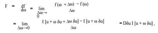
Lemma 1
Show that Dv I[u] = lim
In the
above derivation, no te that operations
and |ω=0 are not interchan geable (as they
both refer to the same variable ω),
while
lim∆ω→0
and |ω=0 are interchangeable, conditional upon sufficient smoothness of I
[u].
Lemma
2 (Lagrange’s formula)
Let I [u] be a functional with
Gateaux derivatives everywhere, and u, u + δu be any points of U.
Then,
I
[u + δu] − I [u ] = Dδu I [u + ǫ δu] 0 < ǫ
< 1.
To prove
Lemma 2, fix u and u + δu in U, and define function f on
R as
f(ω) := I[u
+ ω δu] .
It
follows that
Where Lemma 1 was inv oked. Then,
u s i n g the standard mean-value theorem of calculus,
PIECE WISE CONTINUOUS TRIAL FUNCTION
In weighted residual method the
polynomial and trigonometric series are u sed as trial function. This trial
function is a single composite function and it is valid over the entire
solution domain this assumed trial function solution should match closely to
the exact solution of the differential equation and the boundary conditions, it
i s nothing but a process of curve fitting. This curve fitting is carried out
by piecewise method i.e., the more numbers of piece leads better curve fit. P
iecewise method can be explained by the following si mple problem.
We know that the straight line can be drawn through any two
points. Let, ƒ(x)=sin is the approx imated function for
straight line segments.
![]() One straight line segment
One straight line segment
Two
straight line segment
One
Spring Element
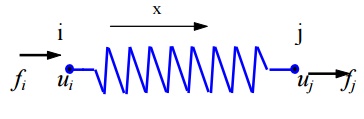
Two
nodes: i, j
Nodal
displacements: ui, uj (in, m, mm)
Nodal
forces: fi, fj (lb, Newton) Spring constant (stiffness): k
(lb/in,
N/m,
N/mm)
Spring
force-displacement relationship:
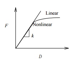
k F / (>
0) is the force needed to produce a unit stretch.
We
only consider linear problems in this introductory course. Consider the
equilibrium of forces for the spring.
At
node 1 we have
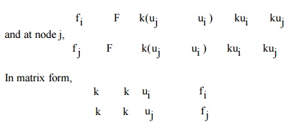
or, where
(element)
stiffness matrix
u = (element nodal) displacement vector
f = (element nodal)
force vector
Note:
That k is
symmetric. Is k singular or non singular? That is, can we solve the equation?
If not, why?
Problem 4
To find
the deformation of the shape
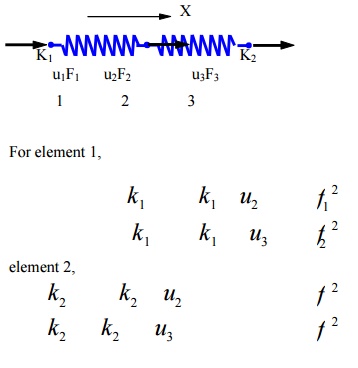
where fI at node 2 F2
M is the (internal) force acting on local node i
of element Consider the quilibrium of forces at node
Checking
the Results
Deformed
shape of the structure
Balance
of the external forces
Order of
magnitudes of the numbers
Notes
about the Spring Elements
Suitable
for stiffness analysis
Not
suitable for stress analysis of the spring itself
Can have spring elements with stiffness in the lateral
direction, Spring elements for torsion, etc.
EXAMPLES OF A BAR FINITE ELEMENT
The
finite element method can be used to solve a variety of problem types in
engineering, mathematics and science. The three main areas are mechanics of
materials, heat transfer and fluid mechanics. The one-dimensional spring
element belongs to the area of mechanics of materials, since it deals with the
displacements, deformations and stresses involved in a solid body subjected to
external loading.
Element dimensionality:
An element can be one-dimensional,
two-dimensional or three-dimensio nal. A spring element is classified as
one-dimensional.
Geometric shape of the element
The
geometric shape of element can be represented as a line, area, or volume. The
one-dimensional spring element is defi ned geometrically as:
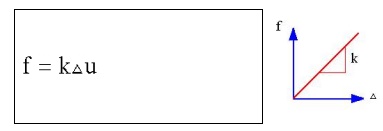
Spring law
The
spring is assumed to b e linear. Force (f) is directly proportional to
deformation (Δ) via the spring constant k, i.e.
Types of degrees of freedom per n ode
Degrees
of freedom are displacements and/or rotations that are associated with a node.
A one-dimensional spring element has two translational degrees of freedom, whi
ch include, an axial (horizontal) displacement (u) at ea ch node.
Element formulation
There are
various ways to mathematically formulate an element. The simplest and limited
approach is the direct method. More mathematically complex and general ap
proaches are energy (variation) and weighted residual methods.
The direct method uses the fundamentals
of equilibrium, compatibility and spring law from a sophomore level mechanics
of material course. We will use the direct method to formulate the
one-dimensional spring element because it is simple and based on a physical
approach.
The direct method is an excellent
setting for becoming familiar with such basis concepts of linear algebra,
stiffness, degrees of freedom, etc., before using the mathematical formulation
approaches as energy or weighted residuals.
Assumptions
Spring deformation
The spring law is a linear force-deformation as
follows:
f = k
f - Spring Force (units: force)
k - Spring Constant (units: force/length)
- Spring
Deformation (units: length)
Spring Behaviour:
A spring
behaves the same in tension and compression.
Spring Stiffness:
Spring
stiffness k is always positive, i.e., k>0, for a physical linear system.
Nodal Force Direction:
Loading is uniaxial, i.e., the
resultant force is along the element. Spring has no resistance to lateral
force.
Weightless Member:
Element
has no mass (weightless).
Node Location:
The geometric location of nodes I
and J cannot coincide, i.e., xi ≠ xj. The
length of the element is only used to visually see the spring.
A column of KE is a
vector of nodal loads that must be applied to an element to sustain a deformed
state in which responding nodal DOF has unit value and all other nodal DOF are
zero. In other words, a column of KE represents an equilibrium
problem.
Example,
uI = 1, uJ = 0.
Spring element has one rigid body mode.
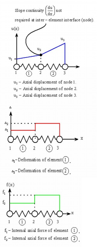
Inter-Element Axial Displacement
The axial displacement (u ) is
continuous through the assembled mesh a nd is described by a linear polynomial
within each el ement. Each element in the mesh may be described by a different
linear polynomial, depending on t he spring rate (k), external loading, and
constraints on the element.
Inter-Element Deformation
The deformation (Δ) is
pi ecewise constant through the assembled mesh and is described by a constant
within each element. Ea ch element in the mesh may be described by a different
constant, depending on the spring constant ( k), external loading, and
constraints on the elem ent.
Inter-Element Internal Axial Forc e
The
internal axial force (f) is piecewise continuous through the assembled mesh
and is described by a constant within eac h element. Each element in the mesh
may be described by a different constant, depending on the spring constant,
external loading, and constraints on the element.
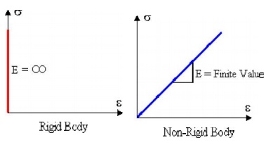
1 Rigid Body
A body is considered rigi d if it
does not deform when a force is applied. Consider rigid and non-rigid bars
subjected to a graduually applied axial force of increasing magnitud e as
shown.
The reader should note the followiing characteristics of rigid
and non-rigid (flexib le) bodies:
·
Force Magnitude - Even if forces are large, a
rigid body does not deform. A non-rigid body will deform even if a force is s
mall. In reality, all bodies deform.
·
Failure - A rigid body does not fail under any
load; while a non-rigid bod y will result either in
ductile or brittle failure w hen the applied load causes the
normal stress t o exceed the breaking (fracture) stress ![]() b of the material. Brittle failure
occurs when the applied load on the non-rigid bar shown above causes the
breaking strength of the bar to be exceeded.
b of the material. Brittle failure
occurs when the applied load on the non-rigid bar shown above causes the
breaking strength of the bar to be exceeded.
·
Material - The material is not considered in a
rigid body. Since a rigid bod y does not deform ( ![]() = 0) this is equivalent to an infinite modulus
of elasticity. In contrast the modulus of elasticity
= 0) this is equivalent to an infinite modulus
of elasticity. In contrast the modulus of elasticity
for a non-rigid material is finite, e.g., for steel, Esteel
= 30 x 106 psi. (20 0 GPa). For rigid and non-rigid bars the
material laws are:
Rigid Body Motion
Rigid body motion occurs when
forces and/or moments are applied to an unrestrained mesh (body), resulting in
motion that occurs without any deformations in the entire m esh (body). Since
no strains (deformations) occur during rigid body motion, there can be no
stresses developed in the mesh.
A rigid body in general can be
subjected to three types of motion, w hich are translation, rotation about a
fixed axis, and general motion which consists of a combination o f both
translation and rotation. These three motion types are as follows:
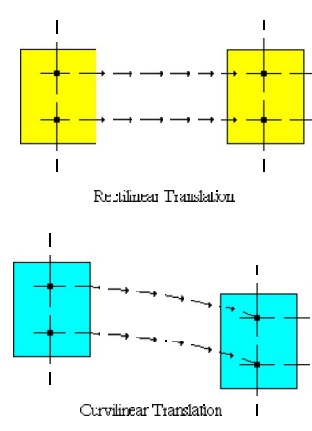
Translation - If any line segment on the body remains parallel
to its original direction during the motion, it is said to be in translation.
When the path of motion is along a straight line, the motion is called rectilinear
translation, while a curved path is considered as a curvilinear translation.
The curvilinear motion shown below is a combination of two translational
motions, o ne horizontal motion and one vertical motion.
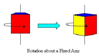
Rotation About a Fixe d Axis - If all the particles of a rigid
body mov e along circular paths, except the ones which lie on the axis of
rotation, it is said to be in rotation ab out a fixed axis.
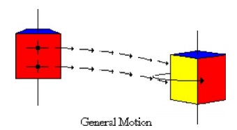
General Motion - Any motion of a rigid body that
consists of the combination of both translations
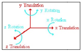
There are six rigid bo dy modes in general three-dimensional
situati on; three translational along the x, y, and z axes and three rotational
about x, y, and z axes. Illustratio ns of these rigid body modes are presented
as follows:
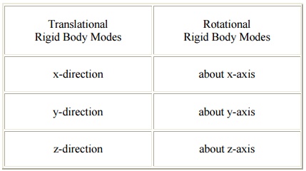
Translational
Rigid Body Modes : Rotational
Rigid Body Modes
x-direction about x-axis
y-direction about y-axis
z-direction about z-axis
1-D
3-NODED QUADRATIC BAR ELEMENT
Problem 6
A single
1-D 3-noded quadratic bar element has 3 nodes with local coordinates as shown
in
Figure
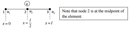
The chosen approximation function for the field variable u
is u = a + bx + cx2
Let the field variable u have values u1 , u2
and u3 at nodes 1, 2 and 3, respectively.
To find
the unknowns a, b and c, we apply the boundary conditions
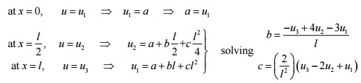
Substituting the values of a, b and c in
equation (1) and collecting the coefficients of u1 , u
2 and u3
u = N1u1 + N 2 u 2 + N 3u3
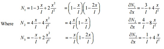
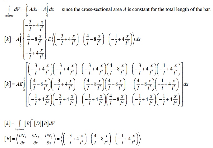
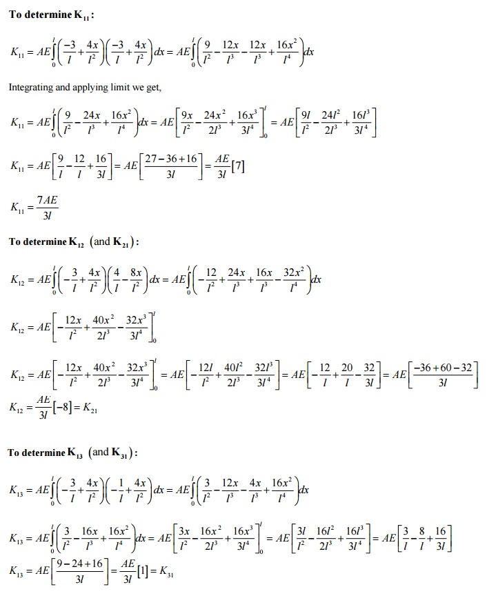
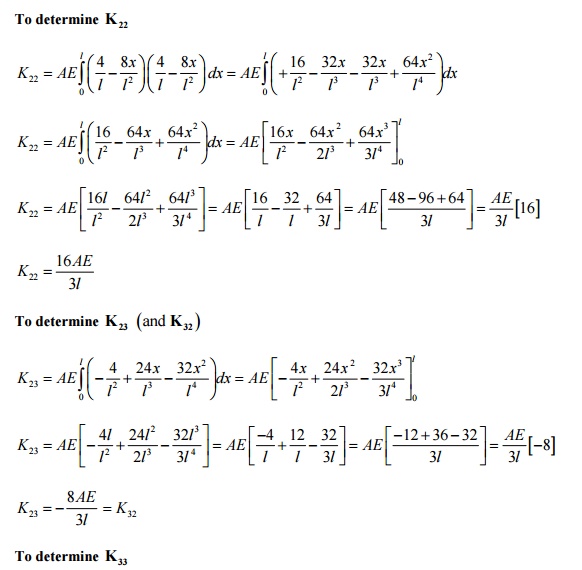
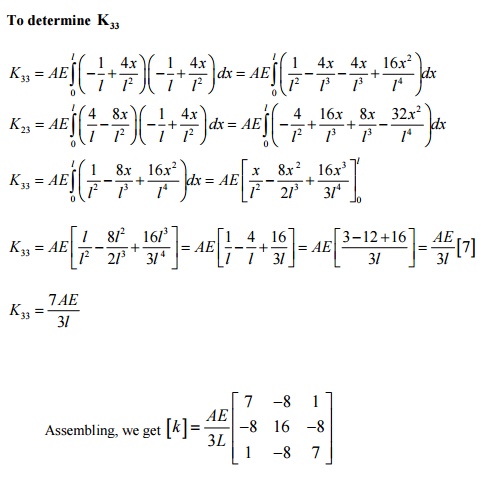
Derivation
of stiffness matrix for 1-D 3-noded quadratic bar element:
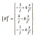
[D ] = E for a bar element (1-D case - only axial stress
(s x ) and strain (e x
) exist Þ s x = Ee x )
PRINCIPLE OF STATIONERY TOTAL POTENTIAL (PSTP)
1 Potential energy in elastic bodies
Potential energy is the capacity
to do the work by the force acting on deformable bodies; the forces acting on a
body may be classified as external forces and internal forces. External forces
are the applied loads while internal force is the stresses developed in the
body. Hence the total potential energy is the sum of internal and external
potential energy.
Consider
a spring mass system let its stiffness be k and length L, due to a force P let
it extend
by u
The load P moves down by distance
u. hence it loses its capacity to do work by P u. the external potential energy
in this case is given by.
H = -P u
Average
force = Ku/2
The energy stored in the spring due to strain = Average force
x Deflection
= Ku/2 x
u
Total potential energy in the spring =
K u2- P u
2 Principle of Minimum Potential Energy
From the
expression for total potential energy
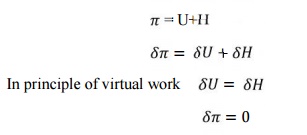
Hence we can conclude that a
deformable body is in equilibrium when the potential energy is having
stationary value.
Hence the principle of minimum
potential energy states among all the displacement equations that internal
compatibility and the boundary condition those that also satisfy the equation
of equilibrium make the potential energy a minimum is a stable system
Problem 7
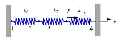
Given: For the spring system shown above,
k1 100 N / mm,
k2 200 N / mm,
k3 100 N / mm
P 500 N,
u1 0
u4 0
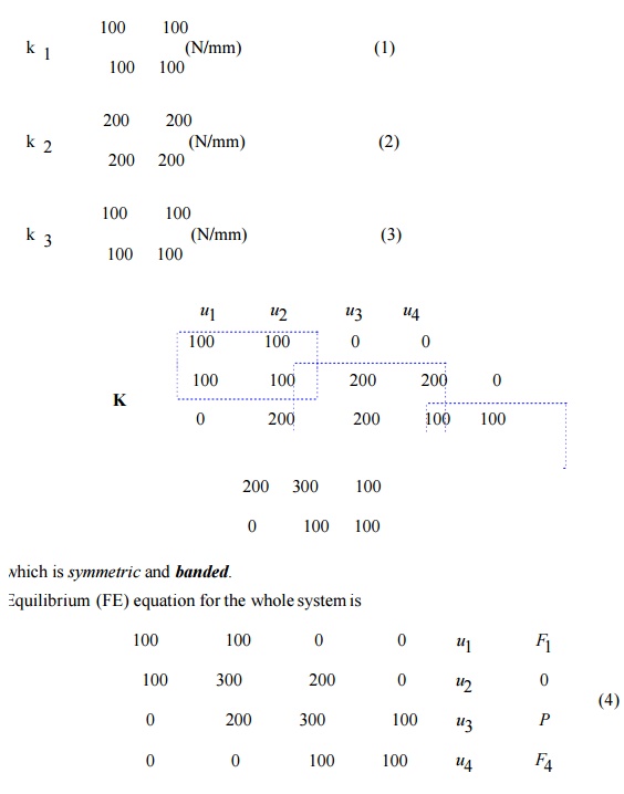
Find: (a) The global stiffness matrix
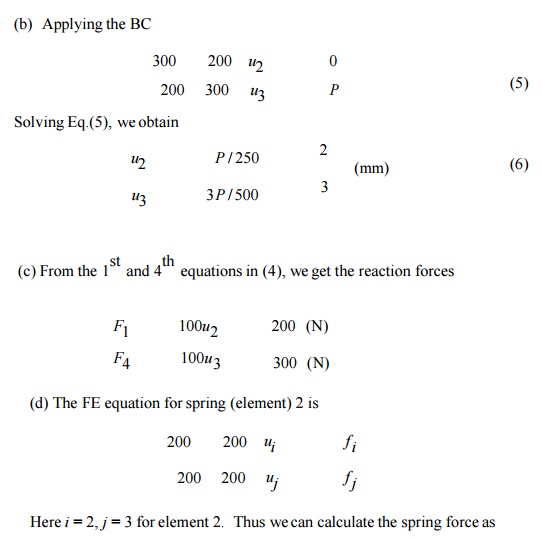
(b) Displacements of nodes 2 and 3
(c) The reaction forces at nodes 1 and 4
(d) the force in the spring 2
Solution:
(a) The element stiffness matrices are
Problem 8
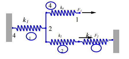
For the spring system with arbitrarily numbered
nodes and elements, as shown above, find the global stiffness matrix.
Solution:
First we
construct the following
Element
Connectivity Table
Element :
Node i (1) : Node j (2)
1 4 2
2 2 3
3 3 5
4 2 1
Which
specifies the global node numbers corresponding to the local node numbers for
each element? Then we can write the element stiffness matrices as follows
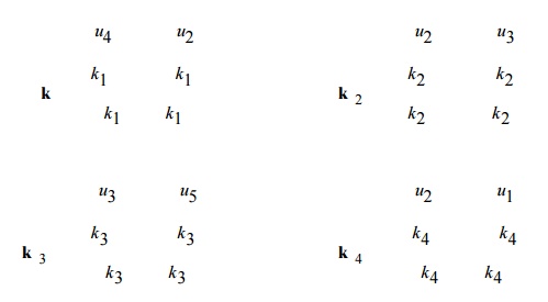
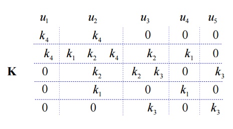
Finally,
applying the superposition method, we obtain the global stiffness matrix as
follows
We may
note that N1 and N2 obey the definition of shape function that is the shape
function will have a value equal to unity at the node to which it belong and
zero value at other nodes.
RAYLEIGH – RITZ
METHOD (VARIATIONAL APPROACH)
It is useful for solving complex structural
problems. This method is possible only if a suitable functional is available.
Otherwise, Galerkin’s method of weighted residual is
used.
Problems (I set)
1. A simply supported beam subjected to uniformly distributed
load over entire span. Determine the bending moment and deflection at midspan
by using Rayleigh – Ritz method and compare with
exact solutions.
2. A bar of
uniform cross section is clamed at one end and left free at another end and it
is subjected to a uniform axial load P. Calculate the displacement and stress
in a bar by using two terms polynomial and three terms polynomial. Compare with
exact solutions.
ADVANTAGES OF FINITE ELEMENT
METHOD
1. FEM can
handle irregular geometry in a convenient manner.
2. Handles
general load conditions without difficulty
3. Non –homogeneous
materials can be handled easily.
4. Higher
order elements may be implemented.
DISADVANTAGES OF FINITE
ELEMENT METHOD
5. It
requires a digital computer and fairly extensive
6. It
requires longer execution time compared with FEM.
7. Output
result will vary considerably.
Related Topics