Chapter: Mechanical : Maintenance Engineering : Repair Methods For Basic Machine Elements
Factors Influencing the Performance of Ball and Rolling Bearing
Factors
Influencing the Performance of Ball and Rolling Bearing
There are many factors that affect the performance
of ball and roller bearings. Some are obvious and some are not very obvious.
This course starts out explaining the performance characteristics of the
various ball and roller bearings. It then deals with some of the aspects
affecting performance such as; how different types of bearing loads can affect
expected life calculations; how the material used and different refining and
heat treatment methods can improve bearing performance; how oil lube film
thickness affects expected life; and what the effect of misalignment and
preloading have on a machine tool bearing application. This course is intended
to enhance the understanding of all the above to ensure that bearing
application engineering will be a more successful venture.
Performance
Characteristics of Rolling Contact Bearings
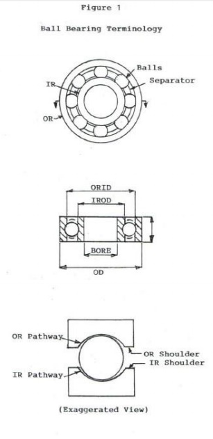
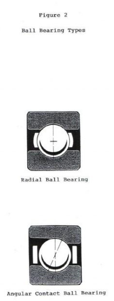
Ball bearings are a common type of a rolling
contact bearing‐. Radial
ball bearings can support radial loads and a lesser amount of bi directional
thrust loads. Angular contact ball bearings can support both radial and thrust
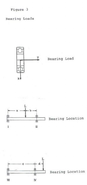
loads and are often used in pairs (See Figures 1, 2 and 3). Because of the much
smaller contact between balls and rings, ball bearings cannot support loads as
heavy as equal sized roller bearings; however, ball bearings can operate with
lower torque and higher speed and precision than roller bearings. Radial ball
bearings can be furnished prelubricated and sealed and can operate for life
without maintenance.
Ball and roller bearings can be furnished with
snap rings installed in grooves in the outer ring outside for mounting
purposes.
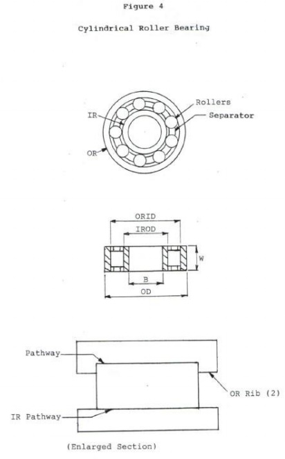
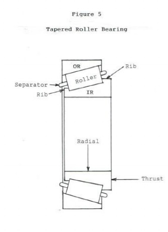
Roller bearings are also a common type of a
rolling bearing. Cylindrical roller bearings can support higher radial loads
than similar size ball bearings but lack the capacity to support substantial
thrust loads. Tapered roller bearings can support
high
radial and high thrust loads and are often used in pairs (See Figures 4 and 5).
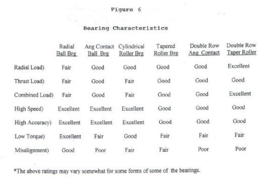
Following is a summary of Figure 6 which has a
table of the characteristics of ball and roller bearings:
• Radial ball bearings have fair
radial and thrust load carrying capability. They are
excellent for high speed, high accuracy, low torque, and good for shaft
misalignment. They can be used on both ends of a shaft. Angular contact ball
bearings have good radial and thrust load carrying capability. They are
excellent for high speed and high accuracy, fair for low torque, but poor for supporting
shafts that are misaligned.
•
Angular contact pairs are good for
radial and thrust loads. They are good for high
speed and accuracy and are poor for supporting shafts that are misaligned. They
are commonly used on both ends of a shaft.
•
Some forms of a cylindrical roller
bearing have good radial load and fair thrust
load carrying capacity. Others are excellent for high speed and
accuracy. All
are fair for
shaft misalignment. Some
forms are good
for
mounting
on both ends of a shaft.
• Tapered roller bearings have
excellent radial and good thrust load carrying capability.
They are good for high speed and accuracy. Tapered roller bearings pairs are
excellent for radial and thrust loads. They are good for accuracy and poor for
misalignment. They too are commonly mounted on both ends of the same shaft.
The equation for calculating the life of a rolling
contact bearing is as follows: L10=3000(C/P)n(500/S)
•
L10 is the life in hours that 90% of
the bearings are expected to endure. This is the
standard equation for all ball and roller bearings.
•
C is the capacity of the bearing in
pounds and is found in industry catalogs. Capacity
is largely dependent on the number and diameter of the rolling elements and the
bearing material.
•
P is the load in pounds that the
bearing is expected to support. Radial loads act
perpendicular to the bearing axis of rotation while thrust loads act parallel
to the bearing axis of rotation. When both types of loads act on the same
bearing, industry catalogs will give an equivalent radial load to be used in
the equation. In most applications, the load is stationary. When the load
rotates with the inner ring, a factor of 1.25 is applied to the load in the
equation because of an increase of stress on the inner ring. When the load
rotates
with the outer ring, no factor is needed. If the load oscillates over
45o, multiply the load times 1.25. Oscillation
less than 45o should be avoided because a condition called “false
brinelling” can occur resulting in
damage
to the bearing rings.
•
n is 3 for ball bearings and 10/3
for roller bearings.
•
S is the speed of rotation of the
bearing in revolutions per minute (rpm). In most
applications, the inner ring rotates while the outer ring is stationary. When
the outer ring rotates and the inner ring is stationary, a factor of 1.25 is
applied to the load because of the additional stress put on the inner ring.
When there are a variety of load and speed conditions for a
given application, the following equation is used
L10=1/(t1/L1+t2/L2+t3/L3+etc.
)
•
L10 is the B10 life of a bearing
operating under a number of different load and speed
conditions.
t1 is the percent time operating under B10 life
condition L1, t2 is the percent time spent under B10 life
condition L2, t3 is the time spend under B10 life condition L3, etc.
Material
and Heat Treatment
The composition, cleanliness and‐ condition of the material used
to fabricate rolling contact bearings have a distinct effect on performance.
The material used for most ball bearings is thru hardened AISI 52100 alloy
steel. The primary
alloying elements are carbon, manganese and
chrome. The high carbon content of 1.04% gives the steel responsiveness to heat
treatment with corresponding very high strength and hardness. The manganese
content of .35% acts as a deoxidizer (purifier) and also imparts strength and
responsiveness to heat treatment. The chrome content of 1.45% increases
response to heat treatment and depth of hardness penetration. An important part
of steel is not only chemical composition, but its cleanliness or freedom from
voids and impurities that come from the iron ore refining process. In bearing
service, steel must withstand compressive stresses up to 500,000 psi.
Impurities and voids in the
steel, especially if they are found in the load
zone of a bearing, can cause an early failure. Many bearing manufacturers use
AISI 52100 “vacuum degassed”. This
process improves
steel cleanliness over “air
melt”
grades eliminating voids
and
reducing the chance of an early failure. For
extremely critical applications such as aircraft and aerospace bearings, “consumable
electrode vacuum melt steel” is
used for even more improved cleanliness and bearing life The
material used for roller bearings is case hardened AISI 8620. The primary
alloying elements are .20% carbon, .80% manganese, .55% nickel, .50% chrome and
.20% molybdenum. Nickel increases strength and toughness while molybdenum adds
to the penetration of hardness and increases toughness. Case hardening involves
heating the steel in a carbon rich atmosphere and quenching it producing a hard
outer case and softer inner core. Roller bearings have a much higher spring
rate than ball bearings‐. The
hard outer case provides support‐of high
compressive stresses while the softer inner core protects against shock loads.
Tests have shown that case hardened steels perform as well as thru hardened
steels. In the past, life improvements factors of 2 for AISI 52100 and 3 for
AISI 8620 have been recommended because of improvements in steel cleanliness.
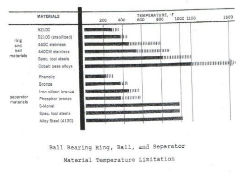
Figure 7 shows the temperature limitation of some common bearing materials.
Ball
bearing rings are processed as follows:
• They are
machined from tubing that is of a special size to reduce cycle time.
• They are
heat treated to a high hardness throughout.
• Every
surface is fine ground.
• The
pathways are honed to an even finer surface finish.
Ball
bearing balls are processed as follows:
• Blanks
are cut from steel wire.
• The
blanks are cold formed into a spherical shape and heat treated.
• The
spheres are ground to a fine finish.
• The
spheres are then honed to a very fine super finish.
• The
finished balls are separated into different diameter class sizes.
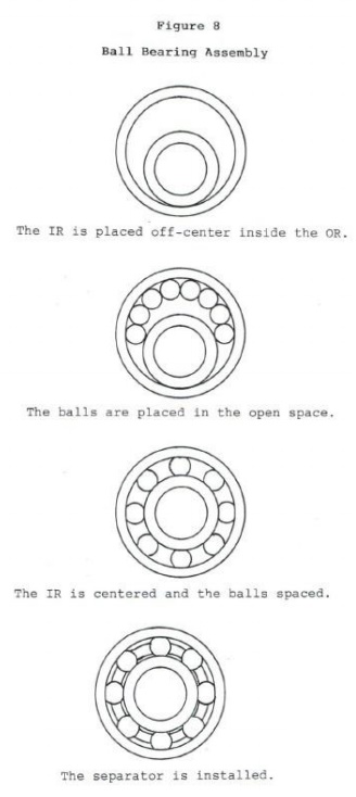
Ball
bearings are assembled as follows:
•
The inner and outer ring pathway
diameters are measured.
•
A compliment of balls is selected
to obtain the correct internal clearance.
•
Radial ball bearings are
assembled according to the Conrad method whereby
the inner ring is placed off center inside the outer ring, the balls loaded in
the crescent space, the rings centered, the balls spaced, and the separator
assembled (See Figure 8).
It has been found that grain flow can have an
effect on bearing life. The raw tubing for rings is extruded which positions
the grain parallel to the tubing central axis. When machining the pathways, end
grain is exposed on the surface of the pathway especially higher up the
shoulder. It has been found that balls running on
end grain have a greater propensity to fail the ring than
balls running on the grain itself. This is particularly true for angular
contact ball bearings where the balls run higher up the pathway shoulder where
end grain is more prevalent than at the center of the pathway where radial
bearings run. Forging or roll forming ring blanks prior to further processing
has been found to minimize exposed end grain resulting in improved bearing
performance.
Lubrication
For normal conditions, the‐ best lubricant to use is mineral
oil which is refined from petroleum. Synthetics have been developed that have
good high temperature and good anti oxidation properties for special
applications but they
don’t form elastohydrodynamic
(EHD) films as well as mineral oils. EHD refers to
the
film of oil that builds up in the load zone between the rolling element and the
rings of rolling contact bearings. It has been found through lab testing that
there are several factors that influence the thickness of the film that builds
up between
the rolling elements and rings. Oil films that are
too thin compared to bearing surface finishes can result in performance less
than predicted, while films that are thicker result in bearing life that
exceeds calculated values.
The
following equation is one that can be used to calculate bearing oil film:
T=B(OS)mL
n
•
T is a measure of oil film
thickness.
•
B is a bearing factor which takes
into account the physical properties of bearings
that influence oil film thickness. B is largely dependent on bearing size with
larger diameter bearings developing thicker oil films. The kind of bearing used
plays a more minor role with standard design ball and roller bearings falling
into the middle of the category.
•
O is an oil factor which is
influenced primarily by oil viscosity at bearing operating
temperature. The type of oil used plays a more minor role with napthenic being
the best, paraffinic lying in the middle, and synthetic being
the worst.
•
S is a speed factor which shows
that higher speeds produce thicker oil films.
•
L is a load factor showing that
higher loads result in thinner oil films.
Graphs of all the above factors have been
developed which make it easy to calculate oil film thickness and its effect on
bearing life. Use of the graphs simplified the equation down to the following:
T=BOSL
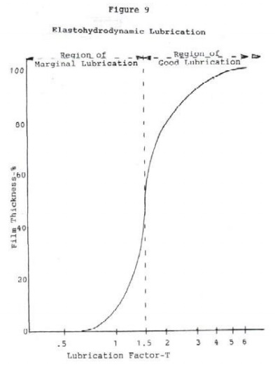
Figure 9 has a graph of oil film thickness vs. T which shows
that T values below 1.5 result in marginal lubrication and above 1.5 result in
good lubrication.
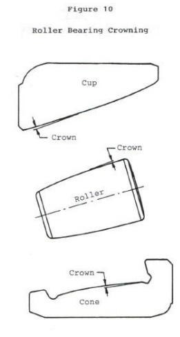
Misalignment refers to the angle made by the
center line of the inner ring with respect to the centerline of the outer ring
in a bearing. When the two centerlines
are collinear, the misalignment is 0o. Normally,
ball bearings can tolerate more misalignment than roller bearings because there
is less chance of a ball contact pattern moving over the top of the race
shoulder than a roller contact moving over the edge the roller. When contact
patterns move over an edge, there is a
high amount of stress concentration which can lead
to early failure. A feature called “crowning” is
applied to rollers and rings to reduce edge loading under
misalignment operation (See Figures 10 and 11).
Normally, cylindrical and tapered roller bearings can tolerate approximately 4
minutes of misalignment while ball bearings can tolerate 16 minutes of
misalignment before serious life reduction occurs.
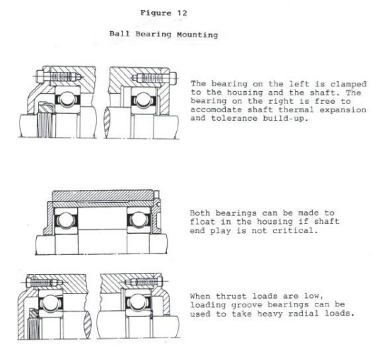
Figure 12 has several different mounting
arrangements for ball bearings. The top sketch has the left bearing fixed in
the housing and the right bearing free to float. This type of mounting
accommodates manufacturing tolerances and shaft thermal expansion without
putting unwanted thrust load on the bearings. The middle sketch has both
bearings free to float when shaft end play is not critical. The lower sketch
has radial ball bearings with loading grooves which are used to load extra
balls in the bearing for added capacity.
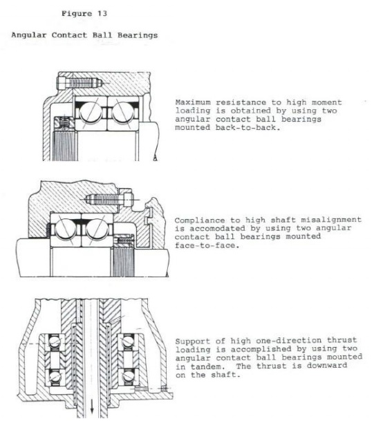
The top sketch‐of‐Figure 13
illustrates how two angular contact ball bearings mounted‐‐“back to back” can be
used to resist shaft misalignment and overturning moments. The middle sketch
has two angular contact ball bearings mounted
“face to
face” to
accommodate shaft misalignment. The lower sketch illustrates
how
two angular contact ball bearings can be mounted in “tandem” to
accommodate
high one direction thrust loads.
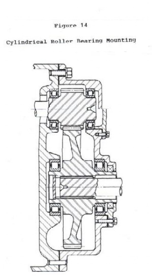
Figure 14 has cylindrical roller bearings supporting a spur
gearset. The two right bearings are mounted differently above and below the
centerline. Above the centerline, the bearings are mounted in the housing cover
which necessitates machining the housing bores separately. Below the
centerline, the bearings are mounted in a separate cap which allows the housing
bores to be machined in one setup providing for better bearing and gear
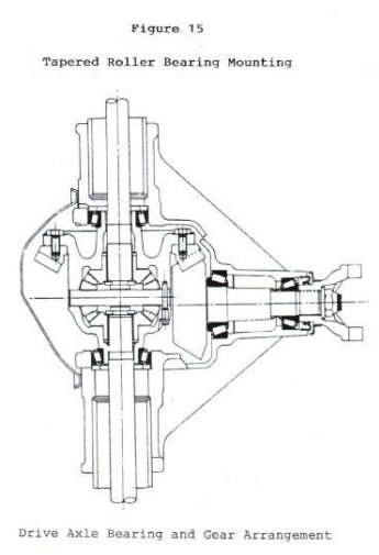
alignment. Figure 15 has tapered roller bearings supporting bevel gears in an
automotive drive axle. The two smaller bearings are nut preloaded while the two
larger bearings are shim preloaded to provide stiff support for the gears.
Preloading
Preloading is a method of mounting bearings on a
shaft, whereby one is thrust loaded against the other. On manufacturing
machines, preloading is done to secure the shaft more rigidly so that the tool
attached to it will machine production parts more accurately.
Figure 16 has a drawing of a machine tool spindle
(small shaft) supported by two angular contact ball bearings. The inner rings
of the two bearings are clamped tightly against the shaft shoulder. Each outer
ring is mounted in its own sleeve. Torquing the nut N puts an axial load on the
right hand bearing through sleeve B.
This load is then transferred through the clamped
inner rings to the left bearing; preloading the bearings and putting the shaft
in tension.
Let
us assume that the nut N is torqued so that a preload of 3000 pounds is put
on the bearings and shaft. Then a work force of
2500 pounds is applied to the right on the front left end of the shaft. This
additional force increases the load on
the front bearing while decreasing the preload
(tension) on the shaft and decreasing the load on the rear bearing. The front
bearing is now supporting less than the preload and the additional work load
(3000+2500=5500 lbs) and the rear bearing is supporting less than the 3000
pound preload.
An analysis will show that the final load on the
front bearing is 4500 pounds and the final load on the rear bearing is 2000
pounds. Both bearings are now operating above the steepest part of their load
vs. deflection curve and are giving the shaft greater support. Without preload,
the 2500 pound work load would have produced a shaft deflection of .003 inch
while with preload, the deflection is down to .001 inch which is a big gain
considering that some ball bearing components have manufacturing machining
tolerances less than .0001 inch.
The calculated life of the left bearing with a
2.1654 inch bore and 4650 pound capacity under a 4500 pound thrust load equals:
L10=3000(4650/3136)10/3(500/1000)=5575
hours
The 3136 pound equivalent radial load was obtained from an
industry catalog. The life of 5575 B10 hours is equivalent to operating the
machine for 2.68 years at 40 hours per week. Angular contact ball bearings are
an excellent choice for supporting machine tool spindles and shafts.
There are many factors that affect the performance
of ball and roller bearings. Some are obvious and some are not very obvious.
This course starts out explaining the performance characteristics of the
various ball and roller bearings.
It then deals with some of the aspects affecting performance such as; how different types of bearing loads can affect expected life calculations; how the material used and different refining and heat treatment methods can improve bearing performance; how oil lube film thickness affects expected life; and what the effect of misalignment and preloading have on a machine tool bearing application. This course is intended to enhance the understanding of all the above to ensure that bearing application engineering will be a more successful venture.

Related Topics