Chapter: Basic Electrical : Electrical Circuits and Measurments
Electrical Circuits
DC Circuits:
A DC circuit (Direct Current circuit) is an
electrical circuit that consists of any combination of constant voltage
sources, constant current sources, and resistors. In this case, the circuit voltages
and currents are constant, i.e., independent of time. More technically, a DC
circuit has no memory. That is, a particular circuit voltage or current does
not depend on the past value of any circuit voltage or current. This implies
that the system of equations that represent a DC circuit do not involve
integrals or derivatives.
If a capacitor and/or inductor is added to a DC
circuit, the resulting circuit is not, strictly speaking, a DC circuit.
However, most such circuits have a DC solution. This solution gives the circuit
voltages and currents when the circuit is in DC steady state. More technically,
such a circuit is represented by a system of differential equations. The
solution to these equations usually contain a time varying or transient part as
well as constant or steady state part. It is this steady state part that is the
DC solution. There are some circuits that do not have a DC solution. Two simple
examples are a constant current source connected to a capacitor and a constant
voltage source connected to an inductor.
In electronics, it is common to refer to a circuit
that is powered by a DC voltage source such as a battery or the output of a DC
power supply as a DC circuit even though what is meant is that the circuit is
DC powered.
Electric Current:
Electric current means, depending on the
context, a flow of electric charge (a phenomenon) or the rate of flow of
electric charge (a quantity). This flowing electric charge is typically carried
by moving electrons, in a conductor such as wire; in an electrolyte, it is
instead carried by ions, and, in a plasma, by both. The SI unit for measuring
the rate of flow of electric charge is the ampere, which is charge flowing
through some surface at the rate of one coulomb per second. Electric current is
measured using an ammeter.
Current:
The flow of charge is called the current and it is the rate at which electric charges pass though a conductor. The charged particle can be either positive or negative. In order for a charge to flow, it needs a push (a force) and it is supplied by voltage, or potential difference. The charge flows from high potential energy to low potential energy.
Current = I = Q / t
Where the symbol I to represent the quantity current.
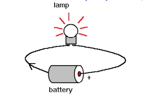
Electro-magnetic force(E.M.F):
Electromotive Force is, the voltage
produced by an electric battery or generator in an electrical circuit or, more
precisely, the energy supplied by a source of electric power in driving a unit
charge around the circuit. The unit is the volt. A difference in charge between
two points in a material can be created by an external energy source such as a
battery. This causes electrons to move so that there is an excess of electrons
at one point and a deficiency of electrons at a second point. This difference
in charge is stored as electrical potential energy known as emf. It is the emf
that causes a current to flow through a circuit.
Voltage:
Voltage is electric potential energy per unit
charge, measured in joules per coulomb ( = volts). It is often referred to as
"electric potential", which then must be distinguished from electric
potential energy by noting that the "potential" is a
"per-unit-charge" quantity. Like mechanical potential energy, the zero
of potential can be chosen at any point, so the difference in voltage is the
quantity which is physically meaningful. The difference in voltage measured
when moving from point A to point B is equal to the work which would have to be
done, per unit charge, against the electric field to move the charge from A to
B.
Electric
potential:
A gravitational analogy
was relied upon to explain the reasoning behind the relationship between
location and potential energy. Moving a positive test charge against the
direction of within Earth's gravitational field. Both movements would be like going
against nature and would require work by an external force. This work would
in turn increase the potential energy of the object. On the other hand, the
movement of a positive test charge in the direction of an electric field would
be like a mass falling downward within Earth's gravitational field. Both
movements would be like going with nature and would occur without
the need of work by an external force. This motion would result in the
loss of potential energy. Potential energy is the stored energy of position of
an object and it is related to the location of the object within a field.
Potential Difference:
A quantity related to
the amount of energy needed to move an object from one place to another against
various types of forces. The term is most often used as an abbreviation of
"electrical potential difference", but it also occurs in many other
branches of physics. Only changes in potential or potential energy (not the
absolute values) can be measured.
Electrical potential
difference is the voltage between two points, or
the voltage drop transversely over an impedance (from one extremity to
another). It is related to the energy needed to move a unit of electrical
charge from one point to the other against the electrostatic field that is
present. The unit of electrical potential difference is the volt (joule per
coulomb). Gravitational potential difference between two points on Earth is
related to the energy needed to move a unit mass from one point to the other
against the Earth's gravitational field. The unit of gravitational potential
differences is joules per kilogram.
Resistance:
Resistance is the ratio
of potential difference across a conductor to the current flowing through it.
If energy is used in passing electricity through an object, that object has a
resistance.
Electromagnetism:
WhatisElectromagnetism?
When current passes
through a conductor, magnetic field will be generated around the conductor and
the conductor become a magnet. This phenomenon is called electromagnetism.
Since the magnet is produced electric current, it is called the electromagnet.
An electromagnet is a type of magnet in which the magnetic field is produced by
a flow of electric current. The magnetic field disappears when the current
ceases. In short, when current flow through a conductor, magnetic field will be
generated.When the current ceases, the magnetic field disappear.
Applications of
Electromagnetism:
Electromagnetism has numerous
applications in today's world of science and physics. The very basic
application of electromagnetism is in the use of motors. The motor has a switch
that continuously switches the polarity of the outside of motor. An
electromagnet does the same thing. We can change the direction by simply
reversing the current. The inside of the motor has an electromagnet, but the
current is controlled in such a way that the outside magnet repels it.
Another very useful application of
electromagnetism is the "CAT scan machine." This machine is usually
used in hospitals to diagnose a disease. As we know that current is present in
our body and the stronger the current, the strong is the magnetic field. This
scanning technology is able to pick up the magnetic fields, and it can be
easily identified where there is a great amount of electrical activity inside
the body.
The work of the human brain is based on
electromagnetism. Electrical impulses cause the operations inside the brain and
it has some magnetic field. When two magnetic fields cross each other inside
the brain, interference occurs which is not healthy for the brain.
Ohm’s
Law:
Ohm's law states that the current
through a conductor between two points is directly proportional to the
potential difference or voltage across the two points, and inversely
proportional to the resistance between them. The mathematical equation that
describes this relationship is:
I= V/R
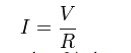
where I is the current through the resistance in
units of amperes, V is the potential difference measured across the resistance
in units of volts, and R is the resistance of the conductor in units of ohms.
More specifically, Ohm's law states that the R in this relation is constant,
independent of the current.
Resistance:
Resistance is the opposition that a
substance offers to the flow of electric current. It is represented by the
uppercase letter R. The standard unit of resistance is the ohm, sometimes
written out as a word, and sometimes symbolized by the uppercase Greek letter
omega. When an electric current of one ampere passes through a component across
which a potential difference (voltage) of one volt exists, then the resistance
of that component is one ohm.
In general, when the applied voltage is
held constant, the current in a direct-current (DC) electrical circuit is
inversely proportional to the resistance. If the resistance is doubled, the
current is cut in half; if the resistance is halved, the current is doubled.
This rule also holds true for most low-frequency alternating-current (AC)
systems, such as household utility circuits.
In some AC circuits, especially at high frequencies,
the situation is more complex, because some components in these systems can
store and release energy, as well as dissipating or converting it.The
electrical resistance per unit length, area, or volume of a substance is known
as resistivity. Resistivity figures are often specified for copper and aluminum
wire, in ohms per kilometre. Opposition to AC, but not to DC, is a property
known as reactance. In an AC circuit, the resistance and reactance combine
vectorially to yield impedance.
Voltage:
Introduction:
The voltage between two points is a short name for
the electrical force that would drive an electric current between those points.
Specifically, voltage is equal to energy per unit charge. In the case of static
electric fields, the voltage between two points is equal to the electrical
potential difference between those points. In the more general case with
electric and magnetic fields that vary with time, the terms are no longer
synonymous.
Electric potential is the energy required to move a
unit electric charge to a particular place in a static electric field.Voltage
can be measured by a voltmeter. The unit of measurement is the volt.
What is voltage?
Voltage should be more correctly called
"potential difference". It is actually the electron moving force in
electricity (emf) and the potential difference is responsible for the pushing
and pulling of electrons or electric current through a circuit.
AC
Circuits:
Fundamentals of AC:
An alternating current (AC) is an electrical
current, where the magnitude of the current varies in a cyclical form, as
opposed to direct current, where the polarity of the current stays constant.
The usual waveform of an AC circuit is generally
that of a sine wave, as this results in the most efficient transmission of
energy. However in certain applications different waveforms are used, such as
triangular or square waves.
Used generically, AC refers to the form in which
electricity is delivered to businesses and residences. However, audio and radio
signals carried on electrical wire are also examples of alternating current. In
these applications, an important goal is often the recovery of information
encoded (or modulated) onto the AC signal.
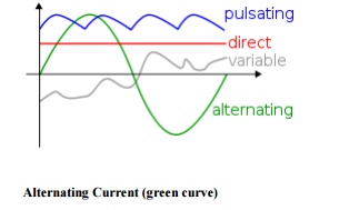
Alternating
Current (green curve)
AC
Instantaneous and RMS:
Instantaneous Value:
The INSTANTANEOUS value of an
alternating voltage or current is the value of voltage or current at one
particular instant. The value may be zero if the particular instant is the time
in the cycle at which the polarity of the voltage is changing. It may also be
the same as the peak value, if the selected instant is the time in the cycle at
which the voltage or current stops increasing and starts decreasing. There are
actually an infinite number of instantaneous values between zero and the peak
value.
RMS Value:
The average value of an AC waveform is
NOT the same value as that for a DC waveforms average value. This is because
the AC waveform is constantly changing with time and the heating effect given
by the formula ( P = I 2.R ), will also be changing producing a
positive power consumption. The equivalent average value for an alternating
current system that provides the same power to the load as a DC equivalent
circuit is called the "effective value". This effective power in an
alternating current system is therefore equal to: ( I2.R.Average ).
As power is proportional to current2
Avesquared,. Therefore, the effective current in an AC system is called the
Root Mean Squared or R.M.S.
RLC
Series Circuit:
An RLC circuit (or LCR circuit) is an electrical
circuit consisting of a resistor, an inductor, and a capacitor, connected in
series. I is the current through the circuit.
VR
= IR, voltage drop across R
VL
= IXL, voltage drop across L
VC= IXC, voltage drop across C
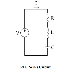
RLC
Series Circuit
DIFFERENCE BETWEEN AC AND DC:
Current that flows
continuously in one direction is called direct current. Alternating current
(A.C) is the current that flows in one direction for a brief time then reverses
and flows in opposite direction for a similar time. The source for alternating current
is called a.c generator or alternator.
Cycle:
One complete set of positive and negative values of an alternating quantity is called
cycle.
Frequency:
The number of cycles
made by an alternating quantity per second is called frequency. The unit of
frequency is Hertz(Hz)
Amplitude or Peak value
The maximum positive or
negative value of an alternating quantity is called amplitude or peak value.
Average value:
This is the average of
instantaneous values of an alternating quantity over one complete cycle of the
wave.
Time period:
The time taken to
complete one complete cycle. Average value derivation:
Let i = the instantaneous value of
current And i = Im sin ɵ
Where, Im is
the maximum value.
Kirchholaw:ff’s
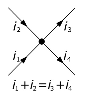
Kirchoff's Current Law:
First law (Current law or Point law):
The sum of the currents
flowing towards any junction in an electric circuit equal to the sum of
currents flowing away from the junction.
Kirchoff's Current law can be stated in words as the
sum of all currents flowing into a node is zero. Or conversely, the sum of all
currents leaving a node must be zero. As the image below demonstrates, the sum
of currents Ib, Ic, and Id, must equal the total current in Ia. Current flows
through wires much like water flows through pipes. If you have a definite
amount of water entering a closed pipe system, the amount of water that enters
the system must equal the amount of water that exists the system. The number of
branching pipes does not change the net volume of water (or current in our
case) in the system.
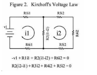
Kirchoff's Voltage Law:
Second
law (voltage law or Mesh law):
In any closed circuit or
mesh, the algebraic sum of all the electromotive forces and the voltage drops
is equal to zero.
Kirchoff's voltage law can be stated in words as the
sum of all voltage drops and rises in a closed loop equals zero. As the image
below demonstrates, loop 1 and loop 2 are both closed loops within the circuit.
The sum of all voltage drops and rises around loop 1 equals zero, and the sum
of all voltage drops and rises in loop 2 must also equal zero. A closed loop
can be defined as any path in which the originating point in the loop is also
the ending point for the loop. No matter how the loopis defined or drawn, the
sum of the voltages in the loop must be zero
Problems
and Calculations:
Problem 1:
A current of 0.5 A is flowing through
the r between its ends.
Solution:
Current
I = 0.5A.
Resistance R = 10Ω Potential difference V = ?
V =
IR
= 0.5
× 10 = 5V.
Problem :2
A supply voltage of 220V is applied to a
flowing through it.
Solution:
Voltage V = 220V
Resistance R = 100Ω
Current I = V/R
= 220/100 = 2.2 A.
Problem : 3
Calculate the resistance of the
conductor if a current of 2A flows through it when the potential difference
across its ends is 6V.
Solution:
Current I = 2A. Potential difference = V
= 6. Resistance R = V/I
=
6 /2
=
3 ohm.
Problem: 4
Calculate
the current and resistance of a 100 W ,200V electric bulb.
Solution:
Power,P = 100W
Voltage,V
= 200V
Power
p = VI
Current
I = P/V = 100/200 = 0.5A
Resistance
R = V /I = 200/0.5 = 400W.
Problem: 5
Calculate the power rating of the heater
coil when used on 220V supply taking 5 Amps.
Solution:
Voltage
,V = 220V
Current ,I = 5A, Power,P = VI = 220 × 5
=
1100W = 1.1 KW.
Problem: 6
A circuit is made of 0.4wire,Ωa 150Ω
bulb and a 120Ω rheo connected in series. Determine the total resistance of the
resistance of the circuit.
Solution:
Resistance of the wire = 0.4Ω Resistance
of bulb = 150Ω Resistance of rheostat = 120Ω
In
series,
Total resistance ,R = 0.4 + 150 +120 =
270.4Ω
Problem :7
In the circuit shown in fig .find the
current, voltage drop across each resistor and the power dissipated in each
resistor.
Solution:
Total resistance of the circuit = 2 + 6
+7 R = 15 Ω
Voltage
,V = 4
5V
Circuit
current ,I = V /R =
45 /15 = 3A
Voltage
drop across 2Ω resistor=IR1 V1
= 3 × 2 = 6 Volts.
Voltage
drop across 6Ω resistor V2 = I R2
=
3 × 6 = 18 volts.
Voltage drop acrossV3=IR3 = 7Ω resistor
=
3 × 7 = 21 volts.
Power
dissipated in R1 is P1 = P R1
=
32 × 2 = 18 watts.
Power
dissipated in R2 is P2 = I2 R2.
=
32 × 6 = 54 watts.
Power
dissipated in R3 is P3 = I2 R3.
=
32 × 7 = 63 watts.
Problem : 8
Three resistances of values 2Ω,3Ω and 5Ω
are co supply .Calculate (a) equivalent resistance of the circuit (b) the total
current of the
circuit
(c) the voltage drop across each resistor and (d) the power dissipated in each
resistor.
Solution:
Total
resistance R = R1 + R2+ R3.
=
2 +3+5 = 10Ω
Voltage = 20V
Total
current I = V/R = 20/10 = 2A.
Voltage
drop acrossV1=IR1 2Ω
resistor
=
2× 2 = 4 volts.
Voltage
drop acrossV2=IR2 3Ω
resistor
=
2 × 3 = 6 volts.
Voltage
drop acrossV3=IR3 5Ω
resistor
=
2 ×5 = 10 volts.
Power dissipated =
in I2R1 2Ω
resistor is P1
= 22 × 2 =
8 watts.
Power dissipated in 3 resistor is P2 = I2 R2.
= 22 × 3 =
12 watts.
Power dissipated in 5 resistor is P3 = I2
R3
= 22 ×
5 = 20 watts.
Problem: 9
A lamp can work on a 50
volt mains taking 2 amps.What value of the resistance must be connected in
series with it so that it can be operated from 200 volt mains giving the same
power.
Solution:
Lamp voltage ,V = 50V
Current ,I = 2 amps.
Resistance of the lamp = V/I = 50/25
= 25
Ω
Resistance connected in
series with lamp = r. Supply voltage = 200 volt.
Circuit current I = 2A
Total resistance Rt= V/I = 200/2 = 100Ω
Rt = R + r
100 = 25 + r
r = 75Ω
Related Topics