Chapter: Physics : Dielectric Materials
Dielectric Materials
Dielectric Materials
1 Introduction
2 Basic Definitions
2.1 Electric flux density (D)
2.2 Permittivity
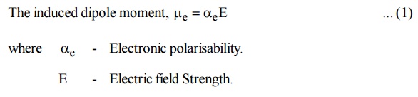
2.3 Dipole moment
2.4 Polarization
2.5 Polarization vector
2.6 Polar and Non-polar Molecules
2.7 Dielectric Constance (or) Relative Permittivity
2.8 Electric Susceptibility
2.9 Different between Polar and Non - Polar molecules
3 Polarization Mechanisms Involved in a Dielectric Material
3.1 Electronic Polarization
3.2 Calculation of electronic polarization
3.3 Electronic polarization
3.4 Ionic Polarization
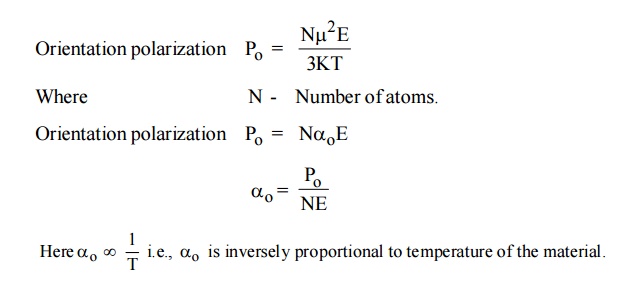
3.5 Orientation Polarization
3.6 Space Charge Polarization
3.7 Total Polarization
4 Frequency and Temperature Dependence of Polarization Mechanism
4.1 Frequency dependence
4.2 Temperature dependence
5 Comparision of Types of Polarisation
6 Internal Field (or) Local Field
6.1 Clausius Mosotti Equations
7 Dielectric Loss
8 Dielectric Breakdown
8.1 Types of dielectric breakdown
9 Ferro – Electricity and Its Applications
9.1 Properties of Ferroelectric Materials
9.2 Hysteresis of Ferroelectric Materials
9.3 Application of Ferroelectric Materials
10 Applications of Dielectric Materials
10.1 Dielectrics in Capacitors
10.2 Insulating materials in transformers
1 INTRODUCTION
Dielectrics are the insulating materials having electric dipole moment permanently or temporarily by applying the electric field. These are mainly used to store electrical energy and used as electrical insulators. All dielectrics are electrical insulators, but all electrical insulators need not to be dielectrics.
Dielectrics are non - metallic materials of high specific resistance and have negative temperature coefficient of resistance.
2 BASIC DEFINITIONS
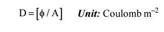
2.1 Electric flux density (D)
The number of electric lines passing through the unit area of cross section.
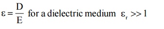
2.2 Permittivity
It is the ratio of electric displacement in a dielectric medium to the applied electric field strength.
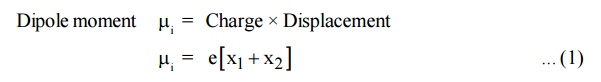
2.3 Dipole moment
Dipole moment is defined as the product of charge and distance between two changes.
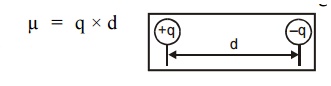
Unit : Coulomb meter.
2.4 Polarization
The separation of negative and positive charges is called polarization. i.e., the i.e., process of producing electric dipoles by an electric field is called polarization

2.5 Polarization vector
If “ ” is the average dipole moment per molecule and “N” is the number of molecules per unit volume then the polarization of the solid is given by the polarization vector P and it can be written as
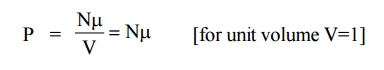
The polarization vector is the dipole moment per unit volume of the dielectric material.
2.6 Polar and Non-polar Molecules
Polar Molecules
Polar Molecules which are having permanent dipole moment even in the absence of an applied field are called polar molecules.
Example: H2O, HCl, CO.
Non-polar Molecules
Molecules which do not have permanent dipole moment, but they have induced dipole moment in the presence of applied electric field are called non - polar molecules.
Example: O2, H2, N2
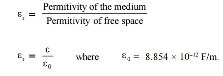
2.7 Dielectric Constance (Or) Relative Permittivity
The dielectric characteristics of a material are determined by the dielectric constant (or) relative permittivity of the material
It is defined as the ratio of the permittivity of the medium to the permittivity of the free space.
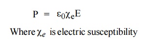
2.8 Electric Susceptibility
The polarization vector P is proportional to the total applied electric field intensity E and is in the same direction of E. Therefore, the polarization vector can be written as
Relation between Electric Susceptibility and relative permittivity
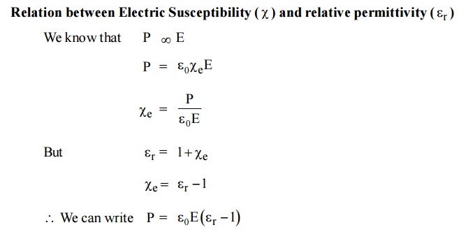
It is a measure of characteristic of every dielectric.
2.9 Different between Polar and Non - Polar molecules
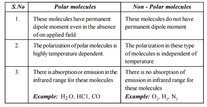
Polar molecules
These molecules have permanent dipole moment even in the absence of on applied field.
The polarization of polar molecules is highly temperature dependent.
There is absorption or emission in the infrared range for these molecules
Example: H2 O, HC1, CO
Non - Polar molecules
These molecules do not have permanent dipole moment
The polarization in these type of molecules is independent of temperature.
There is no absorption of emission in infrared range for these molecules
Example: O2, H2, N2
3 POLARIZATION MECHANISMS INVOLVED IN A DIELECTRIC MATERIAL
There are four different types of polarization.
Electronic (or) induced polarization
Ionic (or) atomic polarization
Orientation (or) dipolar polarization
Space - Charge (or) interfacial polarization
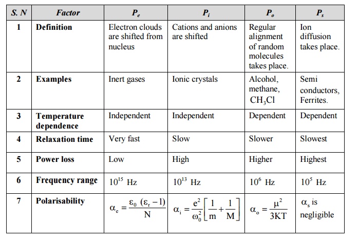
3.1 Electronic Polarization
Electronic Polarization occurs due to the displacement of positively charged nucleus and negatively charged electron in opposite directions by an external electric field. It creates a dipole moment in the dielectric. This is called electronic polarization.
It is proportional to volume of the atoms and is independent of temperature.
3.2 Calculation of electronic polarization(αe)
Consider an atom of a dielectric material of nuclear charge (Ze). The electrons of charge (–Ze) are distributed uniformly throughout the atom (Sphere) of radius R as shown in figure.
With out field
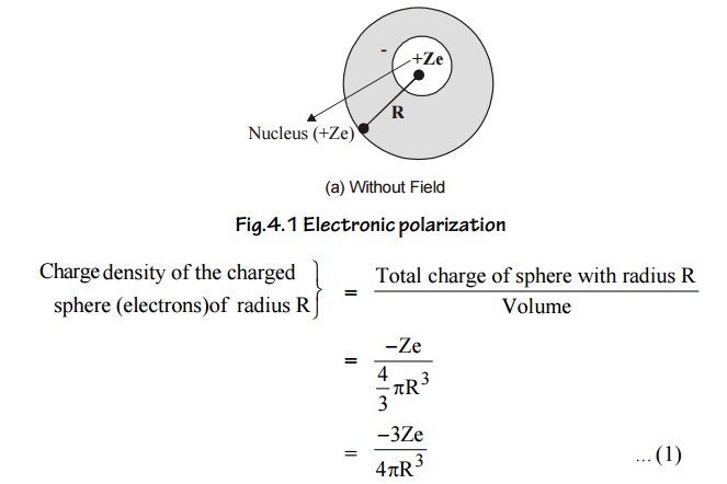
With field
When the atom of the dielectric is placed in an electric field (E), two types of forces are arise.
Lorentz force: Force which separates electrons and positive nucleus due to applied field.
Coulomb force: An attractive force which is produced after separation.
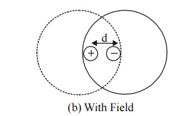
Fig.4.2 Electronic polarization
At equilibrium
Lorentz force = Coulomb force
Lorentz force = (charge of the electron) × (intensity of applied Field)
= (–Ze) (E) ... (2)
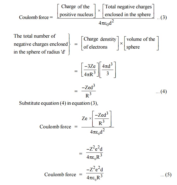
At equilibrium, coulomb force and Lorentz force must be equal and opposite.
Lorentz force (eqn (2)) = Coulomb force (eqn (5))
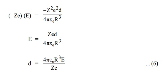
The displacement (d) of electron cloud is proportional to applied field (E).
Now the two electric charges +Ze and –Ze are displaced by a distance d under the influence of the field and form an induced dipole moment which is given by
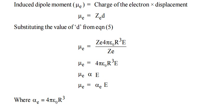
is called electronic polarization which is proportional to volume of the atom.
Conclusion:
Electronic polarization is independent of temperature.
Electronic polarization occurs in all dielectric materials.
It is proportional to the volume of atoms in the material.
3.3 Electronic polarization in terms of ε0 and εr
Pe is the total number of dipoles per unit volume [V=1]
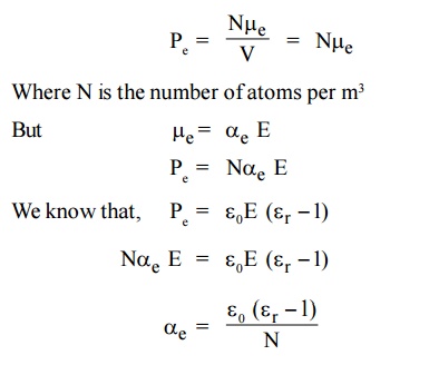
This is called electronic Polarisability
4.3.4 Ionic Polarization
Ionic Polarization which arises due to the displacement of cations (+ve) and anions (-ve) in opposite directions and occurs in ionic solids in the presence of electric field, is called ionic polarization.
Example : NaCl, KCl crystal.
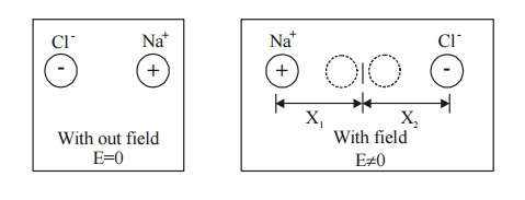
Fig. 4.3 Ionic polarization
Let us assume that there is one cation and one anion present in each unit cell of the ionic crystal (Nacl). When an electric field is applied let X1and X2 be the distance to which positive and negative ions move from their equilibrium positions.
The Resultant dipole moment per unit volume due to ionic displacement is given by,
Dipole moment i = Charge × Displacement
When the field is applied, the restoring force produced is proportional to the displacement.
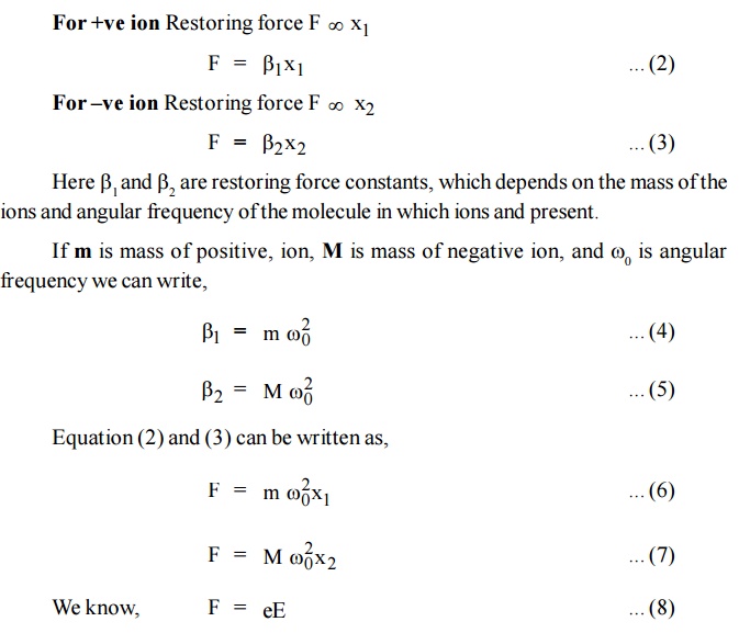
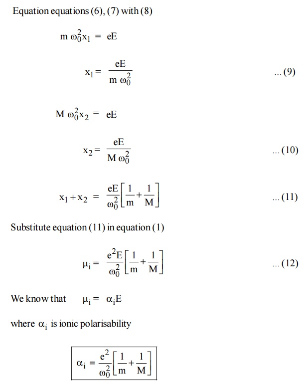
Conclusion:
Ionic polarisability (α i) is inversely proportional to the square of angular frequency of the ionic molecule.
It is independent of temperature.

3.5 Orientation Polarization
The orientation polarization is due to the existence of a permanent dipole moment (polar molecule) in the dielectric medium. Polar molecules have permanent dipole even in the absence of an electric field.
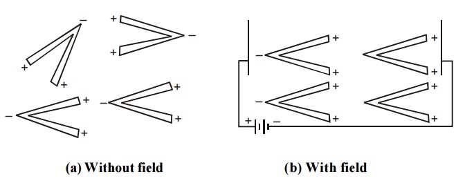
Fig.4.4 Orientation polarization
When an electric field is applied on the dielectric medium with polar molecules, the electric field tries to align these dipoles along its field direction as shown in figure. Due to this there is a resultant dipole moment in that material and this process is called orientation polarization.
This polarization depends on temperature. When the temperature is increased, the dipoles are aligned in random directions.
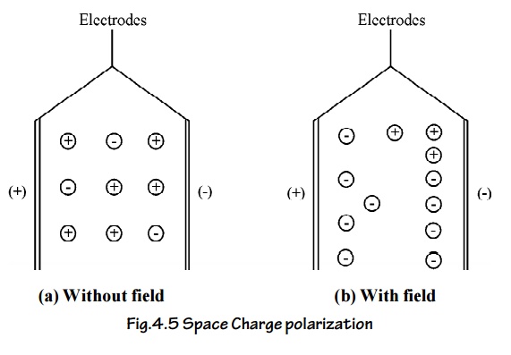
3.6 Space Charge Polarization
The space charge polarization occurs due to the diffusion of ions along the field direction giving rise to redistribution of charges in the dielectric.
Normally this type of polarization occurs in ferrites and semiconductors and it is very small when compared to other types of polarization.
3.7 Total Polarization
The total polarization is the sum of the electronic, ionic orientational and space charge polarization.
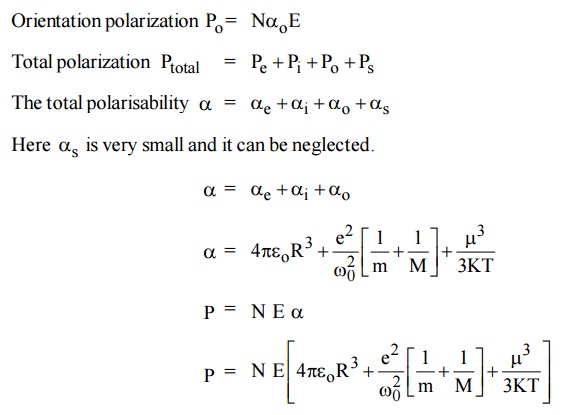
This equation is known as Langevin - Debye equation.
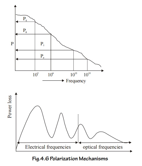
FREQUENCY AND TEMPERATURE DEPENDENCE OF POLARIZATION MECHANISM
4.1 Frequency dependence
On application of an alternating field across the material, the polarization occurs as function of time
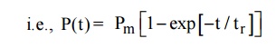
Where Pm is the maximum polarization attained due to applied field and t is the relaxation time. Which is the time taken for a polarization process to reach 0.63 of the maximum value. The relaxation times are different for different kinds of polarization mechanisms.
Electronic polarization is very fast and is completed at any instant of time even when the frequency of the voltage is very high in the optical range (1015 Hz). Thus it occurs at all frequencies.
Ionic Polarization is slower and the ions do not respond when the voltage corresponds to visible optical frequencies, i.e., the electric field changes in polarity at very fast, so that the ions are not able to reorient themselves due up to the field. So the ionic polarization does not occur at visible optical frequencies. It occurs only at frequencies less than 1013 Hz.
Orientation Polarization is even slower than ionic polarization and occurs only at electrical frequencies (audio and radio frequencies 106 Hz).
Space-charge polarization is the slowest process because the ions have to diffuse (jump) over several inter atomic distances. This occurs at very low frequencies of 50 - 60 Hz (power frequencies).
Thus at low frequencies all the four polarizations will occur and the total polarization is very high, but at high frequencies, the value of the total polarization is very small. The following graphs show the frequency dependence of polarization mechanism and the corresponding power losses at those frequencies.
4.2 Temperature dependence
Electronic and ionic polarizations are independent of temperature and the orientation and space charge polarizations are dependent of temperature. Orientation polarization is inversely proportional to the temperature.
Orientation polarization decreases when temperature increases. Because the random nature decreases the tendency of permanent dipoles to align along the field direction. Thus the dielectric constant increases.
Space charge polarization is directly proportional to the temperature. The space charge polarization increases with increase the temperature. It is because of the fact that the thermal energy helps to overcome the activation barrier and the ions diffuse easily, this results in decrease of dielectric constant.
5 COMPARISION OF TYPES OF POLARISATION
6 INTERNAL FIELD (OR) LOCAL FIELD
When a dielectric material is placed in an external electric field, it exerts a dipole moment in it. Therefore two fields are exerted.
Due to external field.
Due to dipole moment
This long range of coulomb forces which is created due to the dipoles is called as Internal field (or) local field. This field is responsible for polarizing the individual atoms (or) molecules.
Lorentz method to find the internal field
The dielectric material which is placed in between two plates of a parallel plate capacitor is uniformly polarized as shown in Figure.
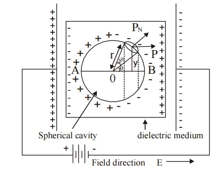
Fig.4.7 Calculation of local field for a cubic structure
Assume an imaginary small spherical cavity around an atom for which the internal field must be calculated at its centre.
The internal field Eint at the atom site (0) can be considered to consist of components namely E1, E2, E3 and E4.
i.e., Eint = E1 + E2 + E3+E4 ... (1)
E1 – Electric field due to charges on this plates of the capacitor.
E2 – Electric field due to the polarised charges (induced charges) on the plane surface of the dielectric.
E3 – Electric field due to polarised charges induced on the surface of the imaginary spherical cavity.
E4 – Electric field due to permanent dipoles of the atoms inside the spherical cavity considered.
Macroscopically, we can take E = E1 + E2 i.e., the field externally applied (E1) and the field induced on the plane surface of the dielectric (E2) can be considered as a single field (E).
If we consider the dielectric which is highly symmetric, then the field due to the dipoles present inside the imaginary cavity will cancel each other. Therefore, the electric field due to permanent dipoles E4=0.
The equation (1) can be written as
Eint = E + E3 ... (2)
Determination of E3
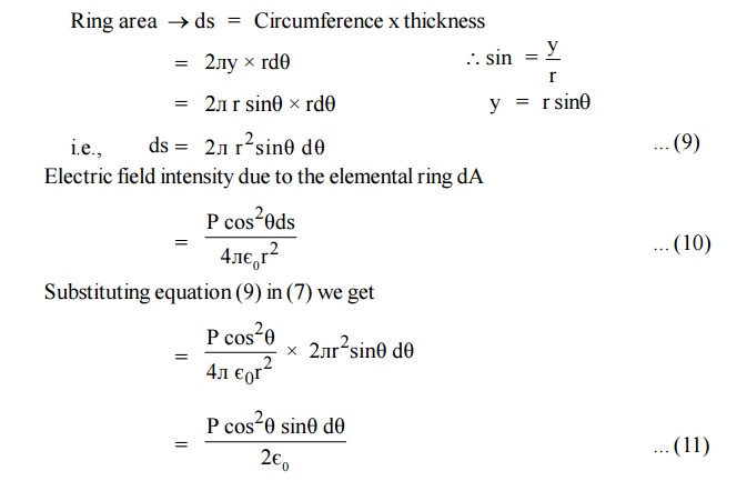
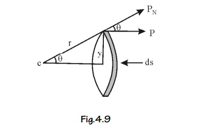
Let us consider a small area ds on the surface of the spherical cavity. This small area makes an angle dθ at the center at an angle θ with the direction of the field E.
The polarization P will be parallel to EPN is the component of polarization perpendicular to the area ds, and q is the charge on the area ds.
Polarization is also defined as the surface charges per unit area.
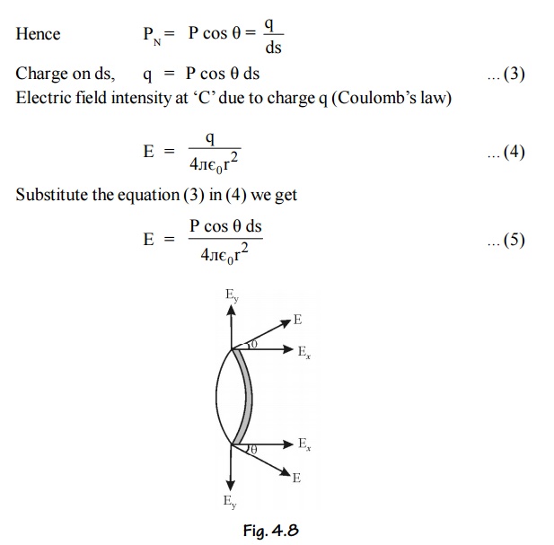
This field intensity is along the radius ‘r’ and it can be resolved into two components as shown in Figure.
The component of intensity parallel to the field direction
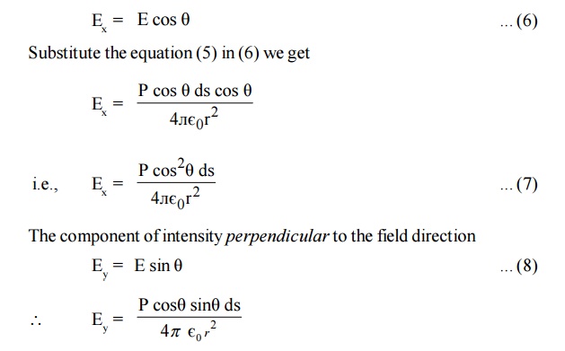
Since the perpendicular components are in opposite direction figure, they cancel out each other. So the parallel components alone are taken into consideration.
Consider a ring area ds which is obtained by revolving ds about AB figure
Ring area ds = Circumference x thickness
Electric field intensity due to charge present in the whole sphere is obtained by integrating equation (11) within the limits 0 to л . This field is taken as E3.
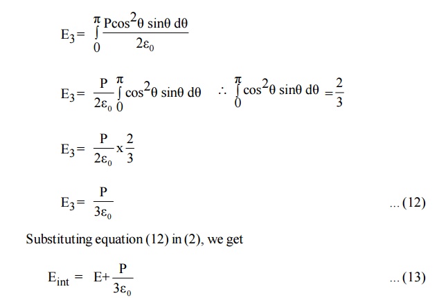
Where Eint is called internal field or Lorentz field.
This equation (13) shows that Eint is different from E. The local intensity Eint is larger than the macroscopic intensity E. So the molecules are more effectively polarsied.
6.1 Clausius Mosotti Equations
If N be the number of molecules per unit volume and á the molecular polarizability then total polarization
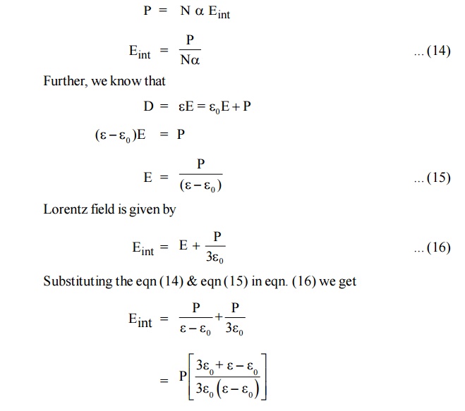
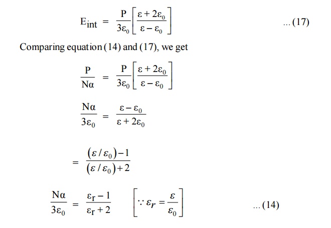
The above equation is Clausius – Mosotti relation, which relates the dielectric constant of the material and polarisability. Thus, it relates macroscopic quantity dielectric constant with microscopic quantity polarisability.
7 DIELECTRIC LOSS
When a dielectric material is subjected to an alternating electric field, some amount of energy is absorbed by the material and is dissipated in the form heat. This loss of energy is called Dielectric loss.
The dielectric loss depends on the type of dielectric medium and the following factors.
i) Temperature ii) Humidity
iii) Applied voltage iv) Frequency
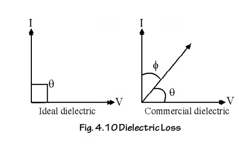
Theory
In an ideal dielectric material, the current leads the voltage by 90°. (i.e. no loss of energy) i.e. = 90°
But in a commercial dielectric material, the current leads the voltage by less than 90°. (i.e., there is loss of energy), i.e., the angle = 90° - is known as the dielectric loss angle.
Consider a dielectric having a capacitance of C and having a voltage V applied to it at a frequency f.
The power loss in the dielectric material is given by P = V I cos
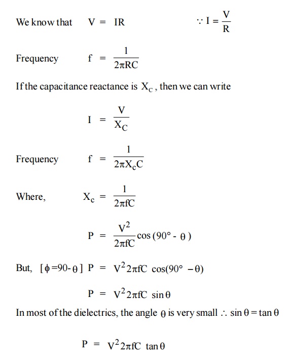
Where tanθ is called the power factor of the dielectric.
It is noted that the power loss will depended on tan θ as long as other factors like voltage, frequency.
Conclusions
The dielectric loss increases with increase of frequency, applied voltage, temperature, and humidity.
The dielectric loss is maximum, when the relaxation time of a polarization process matches the period of the applied AC voltage.
The dielectric loss at radio frequency is high due to diffusion of ions.
The dielectric losses in the optical region, associated with the electrons are referred to as optical absorption. This absorption leads to color of materials.
The dielectric losses in the infrared region associated with the ionic vibrations are referred to as Infrared absorption.
8 DIELECTRIC BREAKDOWN
Definition
When a dielectric material loses its property and permits the flow of a large current, it is said to be dielectric breakdown.
Types of dielectric breakdown
Intrinsic breakdown
Thermal breakdown.
Electrochemical breakdown.
Defect breakdown.
Discharge breakdown.
1. Intrinsic Breakdown
When a dielectric material is subjected to large electric field, a large number of electrons are transferred from the valence band to the conduction band. Thus the dielectric material loses its insulating property and becomes a conductor. This is known as intrinsic breakdown.
Further the conducting electrons may collide with the atoms and release some of the valence electrons. These electrons may collide with some more atoms and may release more electrons. This becomes a chain process resulting in a large current. It is known as avalanche breakdown.
Characteristics
This type of breakdown occurs at room temperature and low temperatures.
This requires relatively large electric fields
This kind of breakdown occurs in the materials.
Thermal breakdown
Thermal breakdown occurs in dielectric when the rate of heat generation is greater than the rate of heat dissipation.
When a dielectric is subjected to an electric field, heat is generation. The generation heat is dissipated by the dielectric material. When the amount of heat generation is higher than the amount of heat dissipation, the temperature inside like dielectric increases and this causes the breakdown called thermal breakdown.
Characteristics:
This can occur only at high temperatures.
The Thermal breakdown time is of the order of few milliseconds.
This requires moderate electric fields.
It depends on size and shape of dielectric material.
Since the dielectric loss its directly proportional to frequency, the electric field strength to create this dielectic breakdown will be smaller for a.c fields and higher d.c fields.
Discharge breakdown
This type of breakdown occurs when the insulator contains occluded gas bubbles. When the dielectic is subjected to an electric field, the gas present in the material will be easily ionized than the solids.
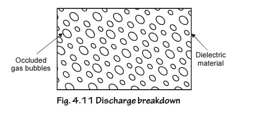
Fig. 4.11 Discharge breakdown
The ionized gas particles bombarded with the solid dielectric and produce large ionization current called discharge breakdown.
Characteristics
This is possible at low voltages where, there are large number of occluded gas bubbles is present in the material.
The life time of the material depends upon the number of discharge taking place inside the material.
This occurs due to presence of gas bubbles.
Electrochemical breakdown
When temperature increases, mobility of ions increases and hence leakage curent also increases. This decreases the insulation resistance and finally creates a dielectric breakdown. Hence this type of breakdown is called electrochemical breakdown.
Characteristics
This is used to determine the leakage current, density of ions and dipoles inside the material.
They are accelerated by high temperatures
This occurs only at low temperature
This type of breakdown occurs even in absence of elcetric field also.
Defect breakdown
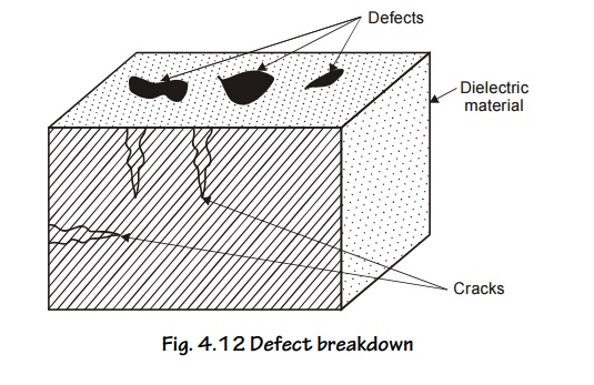
Fig. 4.12 Defect breakdown
If the surface of the dielectric material has defects such as cracks, pores, etc. Moisture and other impurities can fill at these places leading to breakdown, this type of breakdown called Defect breakdown.
Remedies to Avoid Breakdown Mechanisms
To avoid breakdown, the dielectric material should have the following properties
It should have high resistivity.
It must have low dielectric loss and less density.
If should have sufficient mechanical strength.
Thermal expansion should be small.
It should be fire proof.
It must in pure form and not have any defects.
9 FERRO – ELECTRICITY AND ITS APPLICATIONS
Ferro electricity refers to the creation of large induced dipole moment in a weak electric field as well as the existence of electric polarization even in the absence of an applied electric field.
Crystalline dielectric materials which posses a permanent electric polarization are called ferroelectric materials have electric dipole moment even in the absence of any field. Normally they are anisotropic crystals which exhibit spontaneous polarization.
Examples:
Barium Titanate (BaTiO3)
Potassium Dihydrogen Phosphate (KDP)
Ammonium Dihydrogen Phosphate (NH4H2PO4)
Lithium Niobate (LiN6O3)
9.1 Properties of Ferroelectric Materials
Ferroelectric materials exhibits spontaneous polarization i.e., they are polarized even in the absence of electric field.
They exhibit dielectric hysteresis. The lagging of polarization behind the applied electric field is called dielectric hysteresis.
Above ferroelectric Curic temperature, ferroelectric material becomes paraelectric material.
They posses Ferro – electric domain structure.
They can be polarized even by very weak electric field
Ferroelectric materials exhibit piezoelectricity and Pyro electricity. Piezoelectricity means the creation of electric polarization by mechanical stress. Pyro electricity means the creation of electric polarization by thermal stress.
9.2 Hysteresis of Ferroelectric Materials
The ferro electrics are known as non –linear dielectrics. Such materials exhibit hysteresis curve similar to that of ferro magnetic materials.
The lagging of polarization ‘P’ behind the applied electric field E is called dielectric hysteresis.
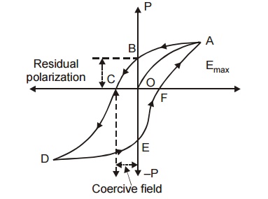
Fig 4.13 Dielectric Hysteresis in ferroelectric materials
When a ferro – electric material is subjected to external electric field (E) the polarization (P) increases with respect to the field applied and it reaches the maximum value ‘OA’.
If now the applied electric field is reduced, the polarization also decreases from a, and when E becomes zero a small amount of polarization exists in the material is called spontaneous (or) residual polarization.
In order to reduce the value of polarization to zero, a reversing electric field oc should be applied. This field is known as coercive field.
Thus the variation of P with respect to E traced along the closed path abcdefa in one full cycle of polarization and depolarization is called hysteresis or the hysteresis curve.
9.3 Application of Ferroelectric Materials
Ferroelectric materials are used to make pressure transducers, ultrasonic transducers, microphones and gas filters.
They are used as memory cores in computers.
They are used to measure and control temperature.
Ferroelectric ceramics are used as capacitors to store electrical energy
They are used to make very good infrared detectors.
Rochelle salt is used in devices like microphones, strain gauges, phonograph pickups and SONAR devices.
In optical communication, the ferroelectric crystals are used for optical modulation.
Ferro electric materials are used to produce ultrasonics
Electrets are also used to bond the fractured bones in human body. 10.They are used as frequency stabilizers and crystal controlled oscillators.
10 APPLICATIONS OF DIELECTRIC MATERIALS
The dielectric materials have three major applications.
It is used as a dielectric medium in capacitors.
It is used as insulating materials in transformers.
It is used in industries and dielectric heating.
10.1 Dielectrics in Capacitors
If dielectrics, to be used in capacitors, it should posse the following properties.
Properties
It must have high dielectric constant
It should posses high dielectric strength
It should also have low dielectric loss.
Applications
Thin sheets of papers filled with synthetic oils are used as dielectrics in the capacitors.
Tissue papers and poly propylene films filled with dielectrol are used in power capacitors.
Mica is used as dielectrics in discrete capacitors.
An electrolytic solution of sodium phosphare is used in wet type electrolytic capacitors.
10.2 Insulating materials in transformers
If dielectrics to act as insulating materials, it should possess the following properties.
Properties
It should have low dielectric constant
It should possess low dielectric loss
It must have high resistance
It must possess high dielectric strength
It should have adequate chemical stability
It must have high moisture resistance
Applications
PVC (Poly Vinyl Chloride) is used to manufacture pipes, batteries, cables etc.
Liquid dielectrics such as petroleum oils, silicone oils are widely used in transformers, circuit breakers etc.
Synthetic oils such as askarels, sovol, etc., are used as a coolant and insulant in high voltage transformers.
Gases such as nitrogen, sulphur hexa fluoride are used in x-ray tubes, switches, high voltage gas filled pressure cables, coolants respectively.
Industrial application
Dielectrics possessing piezoelectric effect is used in gas lighters, microphones, phonographs.
Dielectrics possessing inverse Piezo electric effect is used in quartz watchers, ultrasonic dryers, cleaning the semiconducting wafers, ultrasonic transducer etc.
Dielectric Heating
Dielectric heating is the process of heating the insulating materials at a very high voltage under suitable frequency at which dielectric loss becomes maximum, so that the dielectric loss will come out in the form of heat. Hence adequate heating was done at high voltages.
Dielectric heating is the principle used in microwave oven.
Dielectric heating is also used in the dehydration of food, tobacco etc.
Related Topics