Chapter: Fundamentals of Database Systems : Additional Database Topics: Security and Distribution : Distributed Databases
Data Fragmentation, Replication, and Allocation Techniques for Distributed Database Design
Data Fragmentation,
Replication, and Allocation Techniques for Distributed Database Design
In this section we discuss techniques that are
used to break up the database into logical units, called fragments, which may be assigned for storage at the various sites.
We also discuss the use of data
replication, which permits certain data to be stored in more than one site,
and the process of allocating
fragments—or replicas of fragments—for storage at the various sites. These
techniques are used during the process of distributed
database design. The information concerning data fragmentation,
allocation, and replication is stored in a global
directory that is accessed by the DDBS applications as needed.
1. Data Fragmentation
In a DDB, decisions must be made regarding
which site should be used to store which portions of the database. For now, we
will assume that there is no replication;
that is, each relation—or portion of a relation—is stored at one site only. We
discuss replication and its effects later in this section. We also use the
terminology of relational databases, but similar concepts apply to other data
models. We assume that we are starting with a relational database schema and
must decide on how to dis-tribute the relations over the various sites. To
illustrate our discussion, we use the relational database schema in Figure 3.5.
Before we decide on how to distribute the data,
we must determine the logical units
of the database that are to be distributed. The simplest logical units are the
relations themselves; that is, each whole
relation is to be stored at a particular site. In our example, we must decide
on a site to store each of the relations EMPLOYEE,
DEPARTMENT, PROJECT, WORKS_ON, and DEPENDENT in Figure 3.5. In many cases, however, a relation can be divided into smaller logical
units for distribution. For example, consider the company database shown in
Figure 3.6, and assume there are three computer sites—one for each department
in the company.
We may want to store the database information
relating to each department at the computer site for that department. A
technique called horizontal fragmentation
can be used to partition each relation by department.
Horizontal Fragmentation. A horizontal
fragment of a relation is a subset of the tuples in that relation. The tuples that
belong to the horizontal fragment are specified by a condition on one or more
attributes of the relation. Often, only a sin-gle attribute is involved. For
example, we may define three horizontal fragments on the EMPLOYEE relation in Figure 3.6 with the following conditions: (Dno = 5), (Dno = 4), and (Dno = 1)—each fragment contains the EMPLOYEE tuples working for a particular department. Similarly, we may
define three horizontal fragments for the PROJECT relation, with the conditions (Dnum = 5), (Dnum = 4), and (Dnum = 1)—each fragment contains the PROJECT tuples controlled by a particular department. Horizontal fragmentation divides a
relation horizontally by grouping
rows to create subsets of tuples, where each subset has a certain logical
meaning. These fragments can then be assigned to different sites in the
distributed system. Derived horizontal
fragmentation applies the partitioning of a primary relation (DEPARTMENT in our example) to other secondary relations (EMPLOYEE and PROJECT in our example), which are related to the
primary via a foreign key. This way, related data between the primary and the
secondary relations gets fragmented in the same way.
Vertical Fragmentation. Each site may not need all the attributes of a
relation, which would indicate the need for a different type of
fragmentation. Vertical fragmentation divides
a relation “vertically” by columns. A
vertical fragment of a relation keeps only certain attributes of the
relation. For example, we may want to fragment the EMPLOYEE relation into two vertical fragments. The first fragment includes
personal information—Name, Bdate, Address, and Sex—and the second includes work-related
information—Ssn, Salary, Super_ssn, and Dno. This vertical fragmentation is not quite
proper, because if the two fragments are stored separately, we cannot put the
original employee tuples back together, since there is no common attribute between
the two fragments. It is necessary to include the primary key or some candidate key attribute in every vertical fragment so that the full relation can be
reconstructed from the fragments. Hence, we must add the Ssn attribute to the personal information fragment.
Notice that each horizontal fragment on a relation R can be specified in the relational algebra by a σCi(R) operation. A set of horizontal fragments whose conditions C1, C2, ..., Cn include all the tuples in R—that is, every tuple in R satisfies (C1 OR C2 OR ... OR Cn)—is called a complete horizontal fragmentation of R. In many cases a complete horizontal fragmentation is also disjoint; that is, no tuple in R satisfies (Ci AND Cj) for any i ≠ j. Our two earlier examples of horizontal fragmentation for the EMPLOYEE and PROJECT relations were both complete and disjoint. To recon-struct the relation R from a complete horizontal fragmentation, we need to apply the UNION operation to the fragments.
A vertical fragment on a relation R can be specified by a πLi(R) operation in the
relational algebra. A set of vertical fragments whose projection lists L1, L2, ..., Ln
include all the attributes in R but
share only the primary key attribute of R
is called a complete vertical
fragmentation of R. In this case the projection lists
satisfy the fol-lowing two conditions:
L1 ∪ L2 ∪ ... ∪ Ln
= ATTRS(R).
Li ∩ Lj = PK(R) for any i ≠ j, where ATTRS(R) is the set of
attributes of R and PK(R)
is the primary key of R.
To reconstruct the relation R from a complete vertical fragmentation, we apply the OUTER UNION operation to the vertical fragments (assuming no horizontal fragmentation is used). Notice that we could also apply a FULL OUTER JOIN operation and get the same result for a complete vertical fragmentation, even when some horizontal fragmentation may also have been applied. The two vertical fragments of the EMPLOYEE relation with projection lists L1 = {Ssn, Name, Bdate, Address, Sex} and L2 = {Ssn, Salary, Super_ssn, Dno} constitute a complete vertical fragmentation of EMPLOYEE.
Two horizontal fragments that are neither
complete nor disjoint are those defined on the EMPLOYEE relation in Figure 3.5 by the conditions (Salary > 50000) and (Dno = 4); they may not include all EMPLOYEE tuples, and they may include common tuples. Two vertical
fragments that are not complete are those defined by the attribute lists L1 = {Name, Address} and L2 = {Ssn, Name, Salary}; these lists violate both conditions of a complete vertical
fragmentation.
Mixed (Hybrid) Fragmentation. We can intermix the two types of
fragmentation, yielding a mixed
fragmentation. For example, we may combine the horizon-tal and vertical
fragmentations of the EMPLOYEE relation given earlier into a mixed
fragmentation that includes six fragments. In this case, the original relation
can be reconstructed by applying UNION and OUTER UNION (or OUTER JOIN) operations in the appropriate order. In
general, a fragment of a relation R can be specified by a SELECT-PROJECT combination of operations πL(σC(R)). If
= TRUE (that is, all tuples are selected) and L ≠ ATTRS(R), we get a vertical fragment, and if C ≠ TRUE and L = ATTRS(R), we get a horizontal fragment. Finally, if L ≠ TRUE and L ≠ ATTRS(R), we get a mixed fragment. Notice that a relation can itself be considered a fragment with C = TRUE and L = ATTRS(R). In the following discussion, the term fragment is used to refer to a relation or to any of the preced-ing types of fragments.
A fragmentation
schema of a database is a definition of a set of fragments that includes all attributes and tuples in the
database and satisfies the condition that the whole database can be
reconstructed from the fragments by applying some sequence of OUTER UNION (or OUTER JOIN) and UNION operations. It is also sometimes
useful—although not necessary—to have all the fragments be disjoint except for
the repetition of primary keys among vertical (or mixed) fragments. In the
latter case, all replication and distribution of fragments is clearly specified
at a subsequent stage, separately from fragmentation.
An allocation
schema describes the allocation of fragments to sites of the DDBS; hence,
it is a mapping that specifies for each fragment the site(s) at which it is
stored. If a fragment is stored at more than one site, it is said to be replicated. We discuss data replication
and allocation next.
2. Data Replication and Allocation
Replication is useful in improving the
availability of data. The most extreme case is replication of the whole database at every site in the
distributed system, thus creating a fully
replicated distributed database. This can improve availability remarkably because the system can continue to
operate as long as at least one site is up. It also improves performance of
retrieval for global queries because the results of such queries can be
obtained locally from any one site; hence, a retrieval query can be processed
at the local site where it is submitted, if that site includes a server module.
The disadvantage of full replication is that it can slow down update operations
drastically, since a single logical update must be performed on every copy of
the database to keep the copies consistent. This is especially true if many
copies of the database exist. Full replication makes the concurrency control
and recovery techniques more expensive than they would be if there was no
replication, as we will see in Section 25.7.
The other extreme from full replication
involves having no replication—that
is, each fragment is stored at exactly one site. In this case, all fragments must be dis-joint, except for the
repetition of primary keys among vertical (or mixed) fragments. This is also
called nonredundant allocation.
Between these two extremes, we have a wide
spectrum of partial replication of
the data—that is, some fragments of the database may be replicated whereas
others may not. The number of copies of each fragment can range from one up to
the total number of sites in the distributed system. A special case of partial
replication is occurring heavily in applications where mobile workers—such as
sales forces, financial plan-ners, and claims adjustors—carry partially
replicated databases with them on laptops and PDAs and synchronize them
periodically with the server database.7 A descrip-tion of the replication
of fragments is sometimes called a replication
schema.
Each fragment—or each copy of a fragment—must
be assigned to a particular site in the distributed system. This process is
called data distribution (or data allocation). The choice of sites
and the degree of replication depend on the performance and availability goals of the system and on the types and
frequencies of transactions submitted at each site. For example, if high
availability is required, transactions can be submitted at any site, and most
transactions are retrieval only, a fully replicated database is a good choice.
However, if certain transactions that access particular parts of the database
are mostly submitted at a particular site, the corresponding set of fragments
can be allocated at that site only. Data that is accessed at multiple sites can
be replicated at those sites. If many updates are performed, it may be useful
to limit replication. Finding an optimal or even a good solution to distributed
data allocation is a complex optimization problem.
3. Example of Fragmentation, Allocation, and
Replication
We now consider an example of fragmenting and
distributing the company data-base in Figures 3.5 and 3.6. Suppose that the
company has three computer sites— one for each current department. Sites 2 and
3 are for departments 5 and 4, respectively. At each of these sites, we expect
frequent access to the EMPLOYEE and PROJECT information for the employees who work in that department and the proj-ects controlled
by that department. Further, we assume that these sites mainly access the Name, Ssn, Salary, and Super_ssn attributes of EMPLOYEE. Site 1 is used by company headquarters and
accesses all employee and project information regularly, in addition to keeping
track of DEPENDENT information for insurance purposes.
According to these requirements, the whole
database in Figure 3.6 can be stored at site 1. To determine the fragments to
be replicated at sites 2 and 3, first we can horizontally fragment DEPARTMENT by its key Dnumber. Then we apply derived fragmentation to the EMPLOYEE, PROJECT, and DEPT_LOCATIONS relations based on their foreign keys for
department number—called Dno, Dnum, and Dnumber, respec-tively, in Figure 3.5. We can
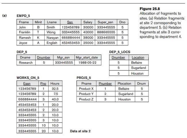
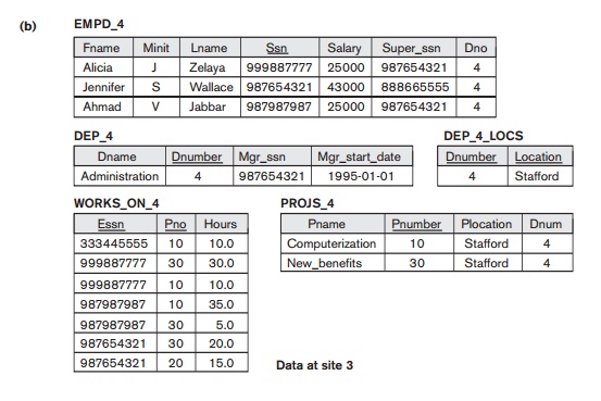
vertically fragment the resulting EMPLOYEE fragments to include only the attributes {Name, Ssn, Salary, Super_ssn, Dno}. Figure 25.8 shows the mixed fragments EMPD_5 and EMPD_4, which include the EMPLOYEE tuples satisfying the conditions Dno = 5 and Dno = 4, respectively. The horizontal fragments
of PROJECT, DEPARTMENT, and DEPT_LOCATIONS are similarly fragmented by department number.
All these fragments—stored at sites 2 and 3—are replicated because they are
also stored at headquarters—site 1.
We must now fragment the WORKS_ON relation and decide which fragments of WORKS_ON to store at sites 2 and 3. We are confronted with the problem that
no attribute of WORKS_ON directly indicates the department to which
each tuple belongs. In fact, each tuple in WORKS_ON relates an employee e to a project P. We could
fragment WORKS_ON based on the department D
in which e works or based on the
department D that controls P. Fragmentation becomes easy if we have
a constraint stating that D = D for all WORKS_ON tuples—that is, if employees can work only on
projects controlled by the department they work for. However, there is no such
constraint in our database in Figure 3.6. For example, the WORKS_ON tuple <333445555, 10, 10.0> relates an employee who works
for department 5 with a project controlled by department 4. In this case, we
could fragment WORKS_ON based on the department in which the employee
works (which is expressed by the condition C)
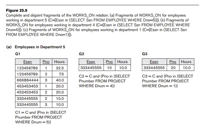
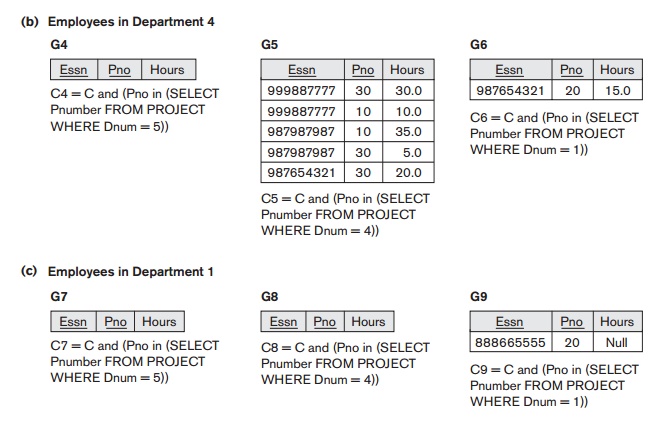
and then fragment further based on the department that controls the projects
that employee is working on, as shown in Figure 25.9.
In Figure 25.9, the union of fragments G1, G2, and G3
gives all WORKS_ON tuples for employees who work for department 5. Similarly, the
union of fragments G4, G5, and G6 gives all WORKS_ON tuples for employees who work for department
4. On the other hand, the union of fragments G1, G4,
and G7 gives all WORKS_ON tuples for projects controlled by department 5. The condition for
each of the fragments G1
through G9 is shown in
Figure 25.9 The relations that represent M:N relationships, such as WORKS_ON, often have several possible logical fragmentations. In our
distribution in Figure 25.8, we choose to include all fragments that can be
joined to


either an EMPLOYEE tuple or a PROJECT tuple at sites 2 and 3. Hence, we place the
union of fragments G1, G2, G3, G4,
and G7 at site 2 and the
union of fragments G4, G5, G6, G2,
and G8 at site 3. Notice that fragments G2 and G4 are replicated at both sites.
This allocation strategy permits the join between the local EMPLOYEE or PROJECT fragments at site 2 or site 3 and the local WORKS_ON fragment to be per-formed completely locally. This clearly
demonstrates how complex the problem of database fragmentation and allocation
is for large databases. The Selected Bibliography at the end of this chapter
discusses some of the work done in this area.
Related Topics