Chapter: Mechanical and Electrical : Thermal Engineering : Air Compressors
Classification of Air Compressors
CLASSIFICATION OF AIR COMPRESSORS
Types of compressors
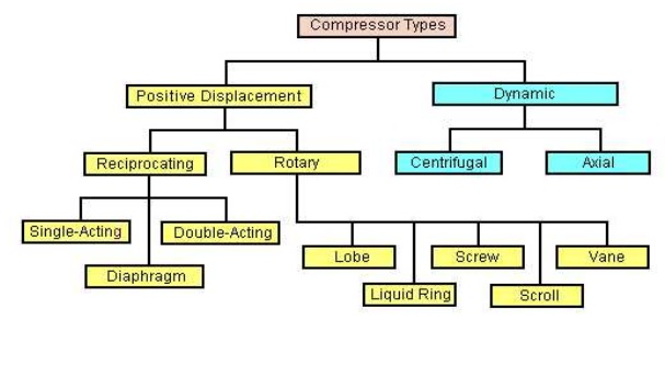
Positive displacement compressor
Ø In the positive-displacement type, a given quantity of air or gas is trapped in a compression chamber and the volume it occupies is mechanically reduced, causing a corresponding rise in pressure prior to discharge.
Ø At constant speed, the air flow remains essentially constant with variations in discharge pressure.
Ø Ex: Reciprocating compressors, vane compressors & so on.
Dynamic compressors:
Ø Dynamic compressors impart velocity energy to continuously flowing air or gas by means of impellers rotating at very high speeds.
Ø The velocity energy is changed into pressure energy both by the impellers and the discharge volutes or diffusers.
Ø In the centrifugal-type dynamic compressors, the shape of the impeller blades determines the relationship between air flow and the pressure (or head) generate.
Ø Ex: centrifugal compressors, axial compressors.
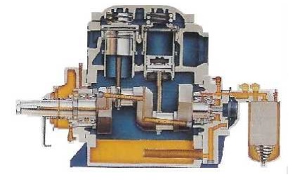
Reciprocating compressors
Ø In a reciprocating compressor, a volume of gas is drawn into a cylinder; it is trapped and compressed by piston, then discharged into the discharge line.
Ø The cylinder valves control the flow of gas through the cylinder; these valves act as check valves.
Principle of Operation
Ø The piston is driven by a crank shaft via a connecting rod.
Ø At the top of the cylinder are a suction valve and a discharge valve.
Ø A reciprocating compres sor usually has two, three, four, or six cylinders in it.
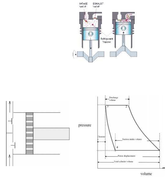
Ø The suction valve opens at point 4.
Ø As the piston travels toward the bottom dead center, the volume of the c ylinder increases and the vapor flows into the cylinder.
Ø The pressure inside the cylinder is slightly less than suction line pressu re. The pressure difference pushes the val ve open on during the suction stroke.
Ø At point 2, the pressure inside the cylinder has become slightly greater than discharge line pressure.
Ø This causes the valve opening allowing the gas to flow out of the cylinder.
Ø The volume continues to decrease toward point 3, maintaining a sufficient pressure difference across the discharge valve to hold it open.
Ø At point 3, the piston reaches the top dead center and reverses direction.
Ø At top dead center, as the piston comes to a complete stop prior to reversing direction, the pressure across the valve is equal.
Ø So, the discharge valve is closed.
Ø As the piston moves towards point 4, the volume increases and the pressure decreases in the cylinder.
Ø The gas trapped in the cylinder expands as the volume increases until to point 4.
Ø At point 4, the gas pressure inside the cylinder becomes less than the suction line pressure, so the suction valve opens again.
Ø The cycle then starts over again.
Ø The shape of the re-expansion line (Line 3-4) is dependent on the same compression exponent that determines the shape of the compression line.
Related Topics