Chapter: Civil : Strength of Materials : Columns
Civil - Strength of Materials - Columns
COLUMNS
1
COLUMNS
If the member of the structure is vertical and
both of its ends are fixed rigidly while
subjected to axial compressive load, the member is known as column.
Example:
A vertical pillar between the roof and floor.
2
STRUTS
If the member of the structure is not vertical
and one (or) both of its ends is Linged (or)
pin jointed, the bar is known as strut.
Example: Connecting rods, piston rods etc,
3 MENTION THE STRESSES WHICH ARE
RESPONSIBLE FOR COLUMN FAILURE.
i.
Direct compressive stresses
ii.
Buckling stresses
iii.
Combined of direct compressive and buckling
stresses.
1.
The column is initially perfectly straight and
the load is applied axially.
2.
The cross-section of the column is uniform
throughout its length.
3.
The
column material is
perfectly elastic, homogeneous
and isotropic and
obeys
Hooke?s law.
4.
The self weight of column is negligible.
4 END CONDITIONS OF
COLUMNS
1.
Both the ends of the column are linged (or
pinned)
2.
One end is fixed and the other end is free.
3.
Both the ends of the column are fixed.
4.
One end is fixed and the other is
pinned.
5 EXPLAIN THE FAILURE OF LONG COLUMN
Solution:
A
long column of uniform cross-sectional area A and of length l, subjected to an
axial compressive load P, as shown in
fig. A column is known as long column if the length of the column in comparison to its lateral
dimensions is very large. Such columns do not fail y crushing alone, but also by bending (also
known buckling)
The load, at which the column just buckles, is
known as buckling load and it is less than
the crushing load is less than the crushing load for a long column.
Buckling load is also known as critical just
(or) crippling load. The value of buckling
load for long columns are long columns is low whereas for short columns
the value of buckling load is high.
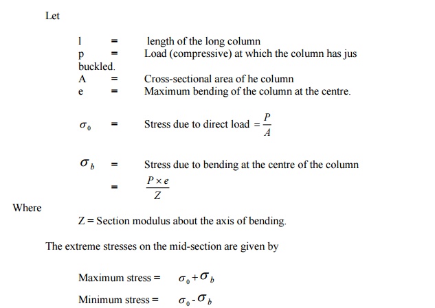
The column will fail when maximum stress (i.e)
s0
+ sb is more the crushing stress fc.
In case of long column, the direct compressive
stresses are negligible as compared to buckling
stresses. Hence very long columns are subjected to buckling stresses.
6 STATE THE ASSUMPTIONS MADE IN THE
EULER'STHEORY.COLUMNAND EXPLAIN THE SIGN
CONVENTIONS CONSIDERED IN COLUMNS.
The following are the assumptions made in
the Euler's column
t
1.
The column is initially perfectly straight and
the load is applied axially
2.
The cross-section of the column is uniform throughout
its length.
3.
The column material is perfectly elastic,
homogeneous and isotropic and obeys
Hooke?s law.
4.
The length of the column is very large as
compared to its lateral dimensions
5.
The direct stress is very small as compared to
the bending stress
6.
The column will fail by buckling alone.
7.
The self-weight of column is negligible.
The following are the sign conventions
considered in columns:
1.
A
moment which will tend to bend the column with its convexity towards its initial centre line is taken as positive.
2.
A
moment which will tend to bend the column with its concavity towards its initial center line is taken as negative.
7 DERIVE THE EXPRESSION FOR CRIP PLING
LOAD WHEN THE BOTH ENDS OF THE COLUMN
ARE HINGED
Solution:
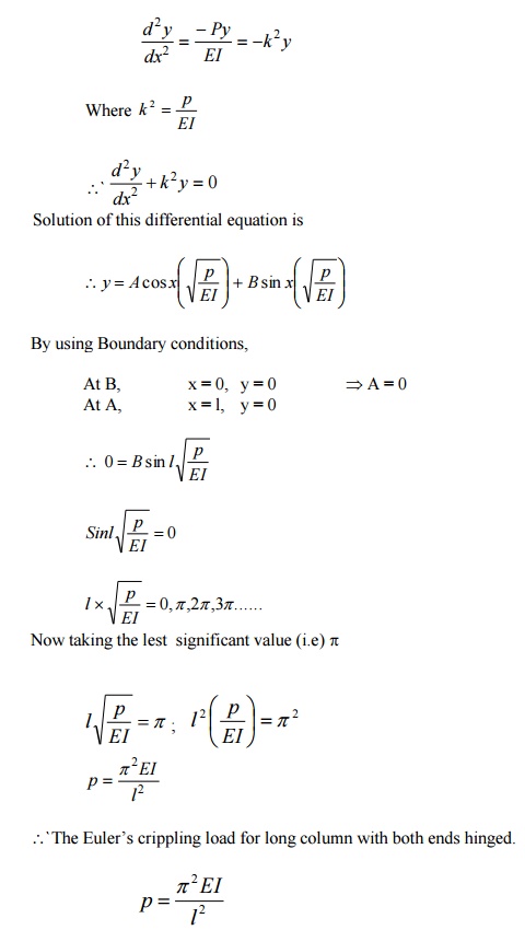
Consider a column AB of length L hinged at
both its ends A and B carries an axial
crippling load at A.
Consider any section X-X at a distance of x
from B.
Let the deflection at X-X is y.
\
The bending moment at X-X due to the load P, M = -P.y
8 DERIVE THE EXPRESSION FOR BUCKLING
LOAD (OR) CRIPPLING LOAD WHEN BOTH ENDS
OF THE COLUMN ARE FIXED
Solution:
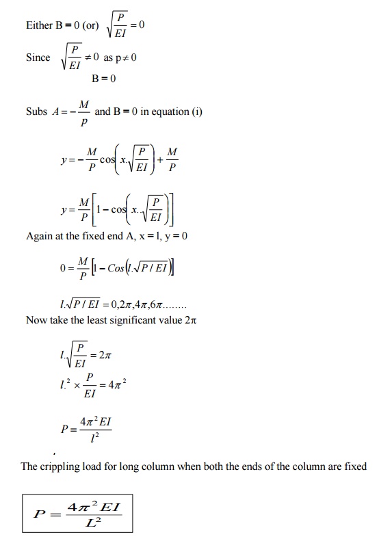
Consider a column AB of length l fixed at both
the ends A and B and caries an axial
crippling load P at A due to which buckling occurs. Under the action of
the load P the column will deflect as shown in fig.
Consider any section
X-X at a distance x from B.Let the deflection at X-X is y.
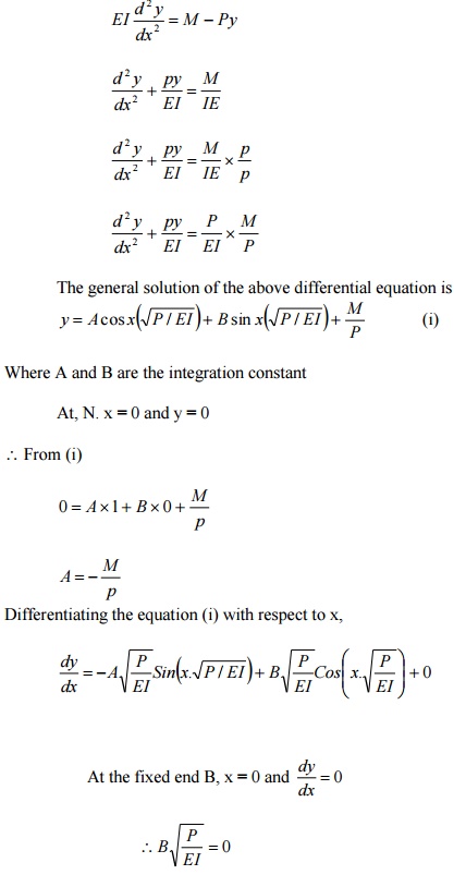
Due to fixity at the ends, let the moment at A
or B is M.
\
Total moment at XX = M -P.y
Differential equation
of the elastic curve is
9 DERIVE THE EXPRESSION FOR CRIPPLING
LOAD WHEN COLUMN WITH ONE END FIXED AND
OTHER END HINGED
Solution:
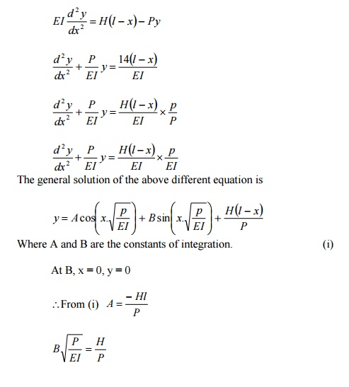
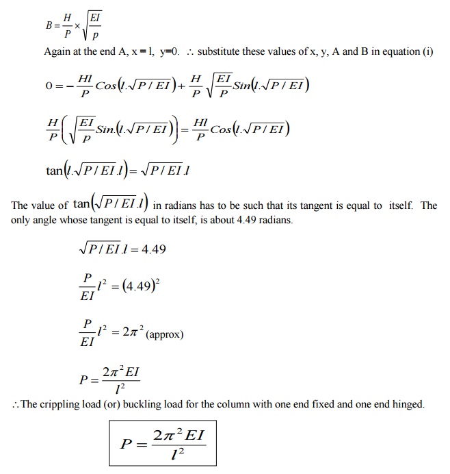
Consider a column AB of length l fixed at B
and hinged at A. It carries an axial crippling
load P at A for which the column just buckles.
As here the column AB is fixed at B, there
will be some fixed end moment at B. Let it be
M. To balance this fixing moment M, a horizontal push H will be exerted
at A.
Consider any section X-X at a distance x from
the fixed end B. Let the deflection at
xx is
y.
Bending moment at xx = H (l-x) - Py
\Differential
equation of the elastic curve is,
10 DERIVE THE EXPRESSION FOR BUCKLING
LOAD FOR THE COLUMN WITH ONE END FIXED
AND OTHER END FREE
Solution:
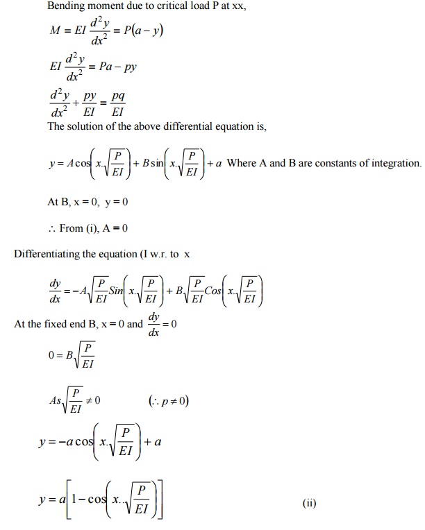
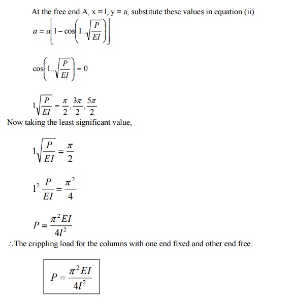
Consider a column AB of length l, fixed
at B and free at A, carrying an axial rippling load P at D de to which it just
buckles. The deflected form of the column AB is shown in fig. Let the new
position of A is A1.
Let a be the deflection
at the free end. Consider any section X-X at a distance x from B.
Let the deflection at xx is y.
Bending moment due to critical load P at xx,
3.11 WRITE THE EXPRESSION FOR CRIPP LING LOAD
WHEN THE BOTH ENDSTHEO COLUMN ARE HINGED

P = Crippling load
E = Young?s
Modulus
I = Moment of inertia
l = Length of column
12 EXPRESSION
FOR BUCKLING LOAD (OR) CRIPPLING LOAD WHEN BOTHDSEN OF THE COLUMN ARE FIXED

P = Crippling load
E = Young?s Modulus
I = Moment of
inertia
l = Length of column
13 EXPRESSION
FOR CRIPPLING LOAD WHEN COLUMN WITH ONE END FIXED AND OTHER END LINGED

P = Crippling load
E = Young?s Modulus
I = Moment of
inertia
l = Length of column
14 EXPRESSION
FOR BUCKLING LOAD FOR THE COLUMN WITH ONE FIXED AND OTHER END FREE

P = Crippling load
E = Young?s Modulus
I = Moment of
inertia
l = Length of column
15
EXPLAIN EQUIVALENT LENGTH (OR) EFFECTIVE LENGTH
If l is actual length of a column, then its
equivalent length (or) effective length L may be obtained by multiplying it with some constant
factor C, which depends on the end fixation of the column (ie) L = C x l.
16 WRITE THE
EQUIVALENT LENGTH (L) OF THE COLUMN IN WHICH BOTH ENDS HINGED AND WRITE THE CRIPPLING LOAD
P = Crippling load
E = Young?s Modulus
I = Moment of
inertia
l = Length of column
17 WRITE THE
RELATION BETWEEN EQUIVALENT LENGTH AND ACTUAL
LENGTH FOR ALL END CONDITIONS OF COLUMN.

A
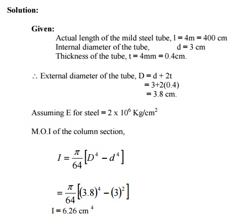
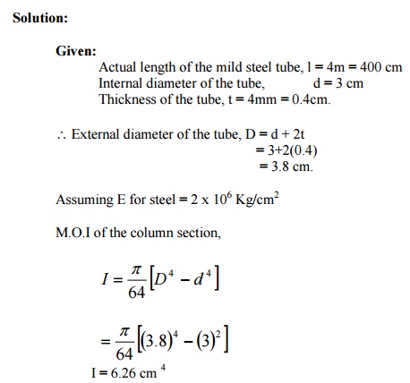
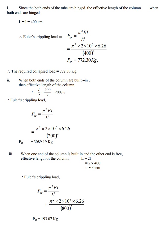
mild steel tube 4m long, 3cm internal diameter and 4mm thick is used as a strut
with both ends hinged. Find the
collapsing load, what will be the crippling load if
i.
Both ends are built in?
ii.
One end is built -in and one end is free?
A
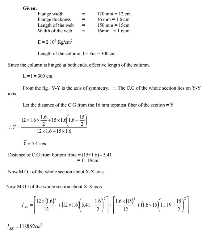
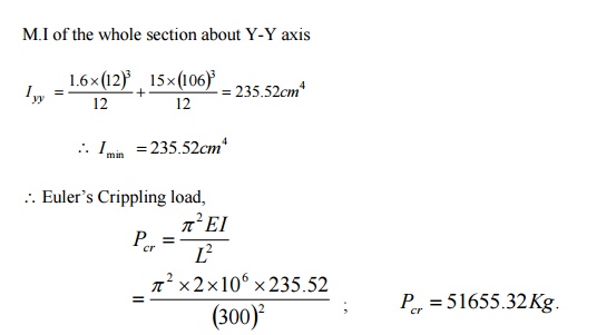
column having a T section with a flange 120 mm x 16 mm and web 150 mm x 16 mm
is 3m long. Assuming the column to be
hinged at both ends, find the crippling load by
6 2
using
Euler's forKg/cmula.. E
= 2 x 10
A
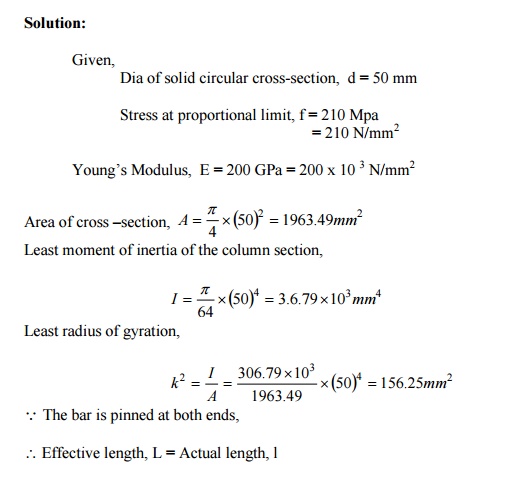
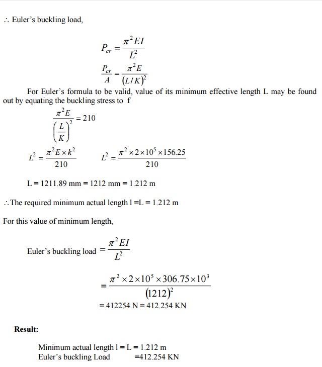
steel bar of solid circular cross-section is 50 mm in diameter. The bar is
pinned at both ends and subjected to
axial compression. If the limit of proportionality of the material is
210 MPa and E = 200 GPa, determine the m
minimum length to which Euler' formula
is valid. Also determine the value
minimum length.
19
CORE (OR) KERNEL OF A SECTION
When a load acts in such a way on a region
around the CG of the section So that in that
region stress everywhere is compressive and no tension is developed
anywhere, then that area is called the core (or) Kernal of a section. The
kernel of the section is the area within which the line of action of the
eccentric load P must cut the cross-section if the stress is not to become
tensile.
20
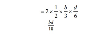
DERIVE THE EXPRESSION FOR CORE OF A RECTANGULAR SECTION
The limit of eccentricity of a rectangular
section b x d on either side of XX axis (or) YY
axis is d/6 to avoid tension at the base core of the rectangular
section.
Core of the rectangular section = Area of the
shaded portion
21 DERIVE THE EXPRESSION FOR CORE OF A
SOLID CIRCULAR SECTION OF DIAMETER D
The limit of eccentricity on either side of
both XX (or) YY axis = D/8 to avoid tension of
the base.
Core of the circular section = Area of the shaded portion

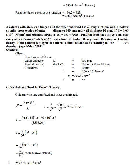
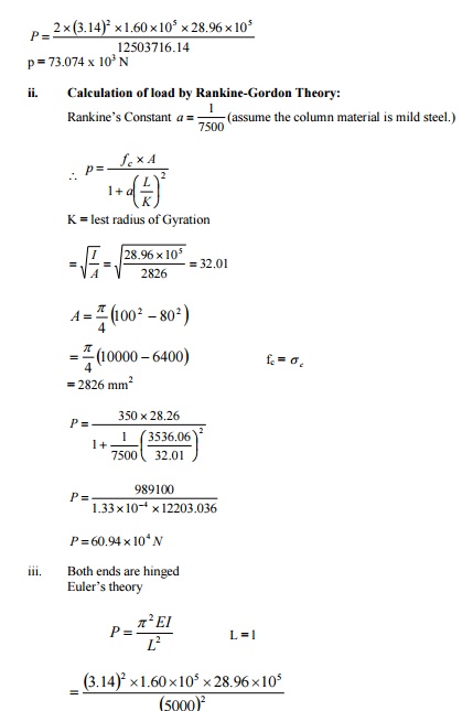
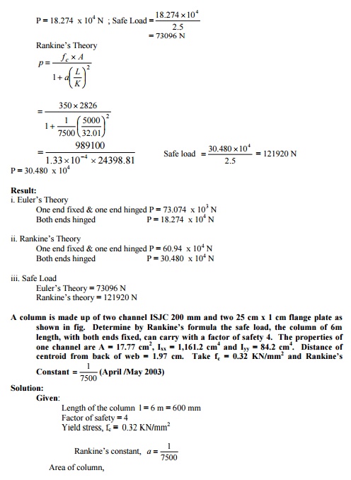
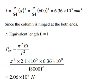
23 A STEEL COLUMN IS OF LENGTH 8M AND
DIAMETER 600 MM WITH BOTH ENDS HINGED.
DETERMINE THE CRIPPLING LOAD BY EULER'S
FORMUL
A. Take E
=2.1´105
N/mm2.
24
SLENDERNESS RATIO
It is defined as the
ratio of the effective length of the column (L) to the least radius of gyration of its cross -section (K) (i.e) the
ratio of L/K is known as slenderness ratio.
Slenderness ratio = L/K
STATE THE LIMITATIONS
OF EULER'S FORMULA

25 WRITE THE
RANKINE'S FORMULA FOR
COLUMNS
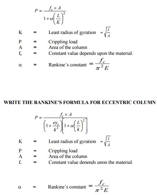
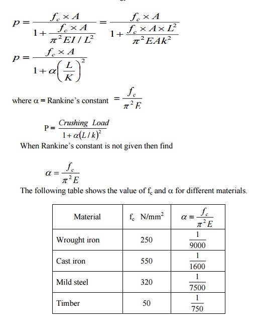
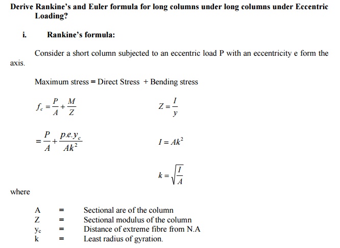
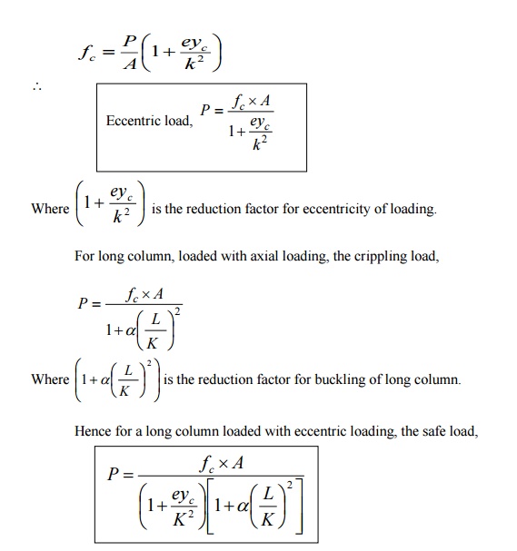
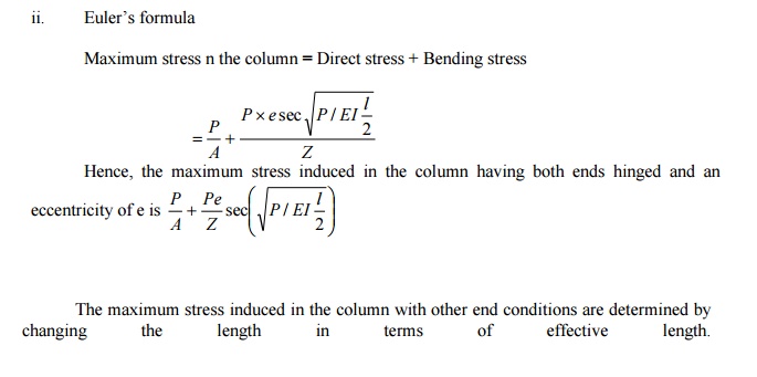
Explain Rankine's and Formula Derive the
Rankine's formula column.
Solution:
Rankine's
Formula:
Euler?s formula gives correct results onl buckling. Whereas Rankine?smulabasedon
practicaldevisedexperiments foran empi
determining the crippling or critical load which is applicable to all
columns irrespective of
whether they a short or long.
If P
is the crippling
load by Rankine?s
form
Pc is the crushing load of the
column material
PE is the crippling load by Euler?s
formula. Then the Empirical formula
devised by Rankine
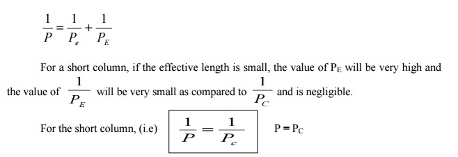
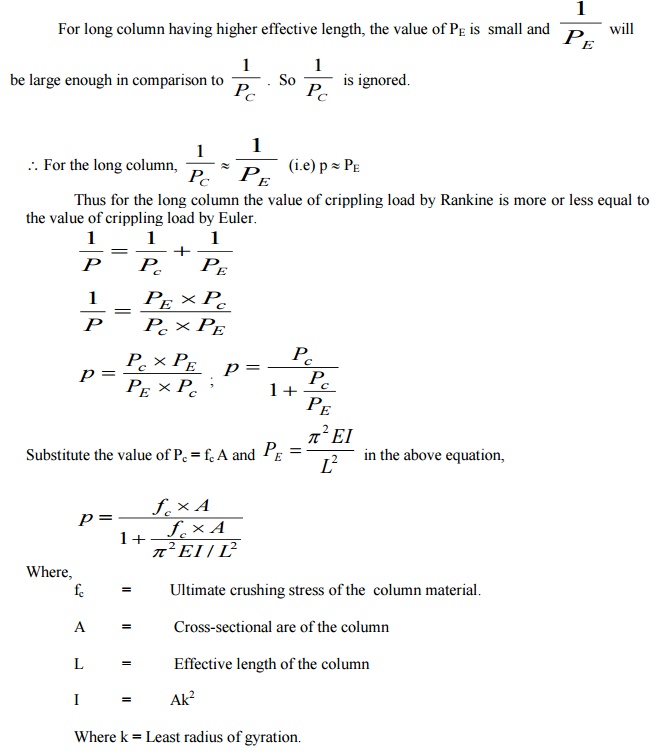
Thus for the short column, value of crippling
load by Rankine is more or less equal to the
value of crushing load:
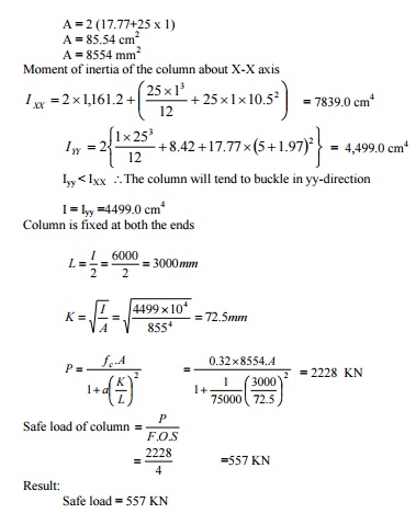
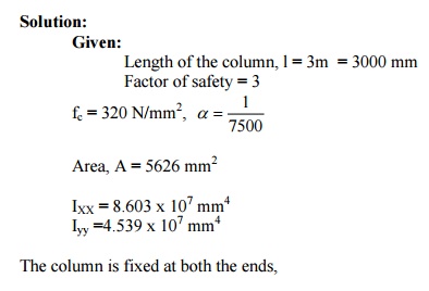
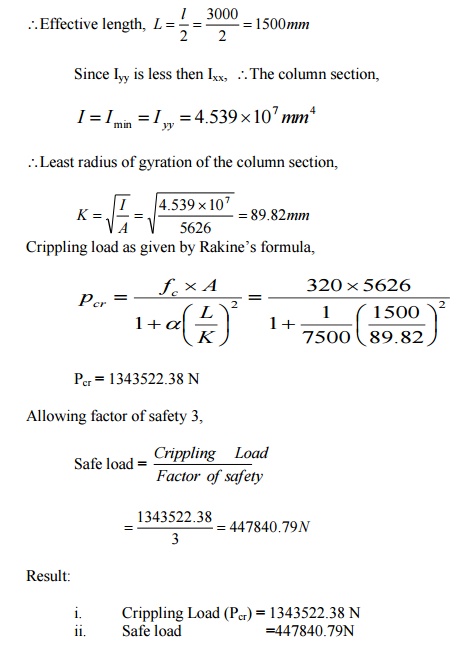
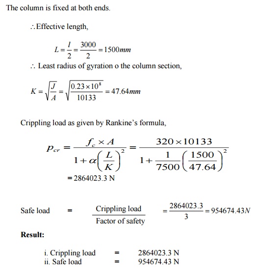
A rolled steel joist ISMB 300 is to be used a
column of 3 meters length with both ends fixed.
Find the safe axial load on the column. Take factor of safety 3, fc
= 320 N/mm2 and a = 1/7500 . Properties of the column section. Area = 5626 mm2, I XX = 8.603 x 107 mm4
Iyy =4.539 x 10⁷
mm4
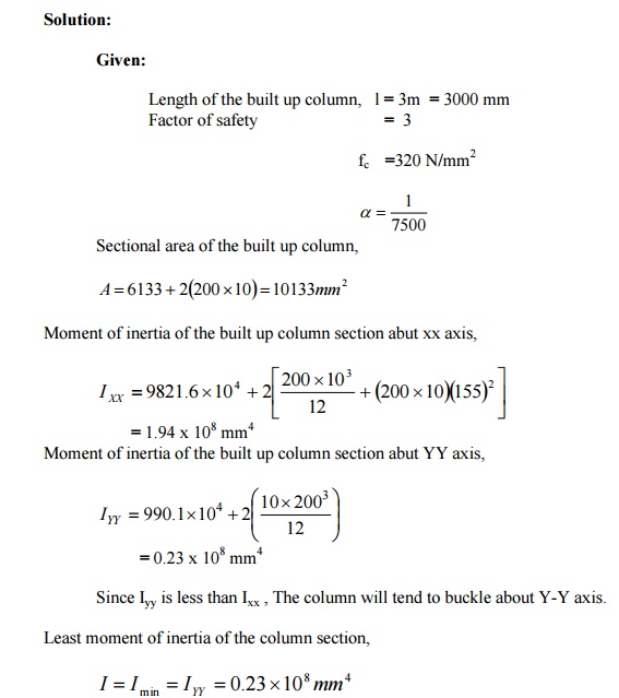
A built up column consisting of rolled steel beam ISWB 300 with two plates 200 mm x 10 mm connected at the top and bottom flanges. Calculate the safe load the column carry, if the length is 3m and both ends are fixed. Take factor of safety 3 fc = 320 N/mm2 and a ? = 1 / 7500 Take properties of joist: A = 6133 mm2 IXX = 9821.6 x 104 mm4 ; Iyy = 990.1 x 104 mm4
A
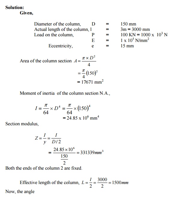
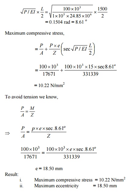
column of circular section has 150 mm dia and 3m length. Both ends of the
column are fixed. The column carries a
load of 100 KN at an eccentricity of 15 mm from the geometrical axis of the column. Find the
maximum compressive stress in the column
section. Find also the maximum permissible eccentricity to avoid tension
in the column section. E = 1 x 10⁵
N/mm2
1.
The
assumptions involved theory. in
Lame's T
i.
The material of the shell is homogenous and
isotropic
ii.
Plane sections normal to the longitudinal axis
of the cylinder remain plane after the
application of internal pressure.
iii.
All the fibres of the material expand (or)
contract independently without being
constrained by their adjacent fibres.
2
Derivation of
Lame's Theory
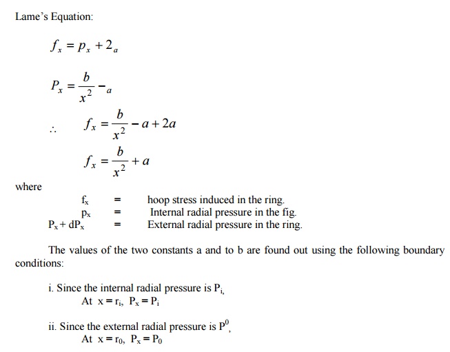
Consider a thick
cylinder
Let
rc=
Inner radius of the cylinder
r0=
Outer radius of the cylinder
Pi=
Internal radial pressure
Po=
External radial pressure
L = Length of the cylinder
f2 = Longitudinal stress.
26
THICK CYLINDER
If the ratio of thickness of the internal
diameter of a cylindrical or spherical shell exceeds 1/20, it is termed as a thick shell.
The hoop stress developed in a thick shell
varies from a maximum value at the inner
circumference to a minimum value at the outer circumference.
Thickness > 1/20
j.
The material of the shell is Homogeneous and
isotropic.
ii.
Plane section normal to the longitudinal axis
of the cylinder remains plane after the
application of internal pressure.
iii.
All the fibers of the material expand (or)
contact independently without being
constrained by there adjacent fibers.
27 MIDDLE THIRD RULE
In rectangular sections, the eccentricity „e?
must be less than o greatest
eccentricity of the load is b/6 form the axis Y-Y and with respect to axis X -X1
the eccentricity does not exceed d/6.
Hence the load may be applied with in the middle third of the base (or) Middle d/3.
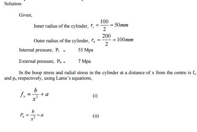
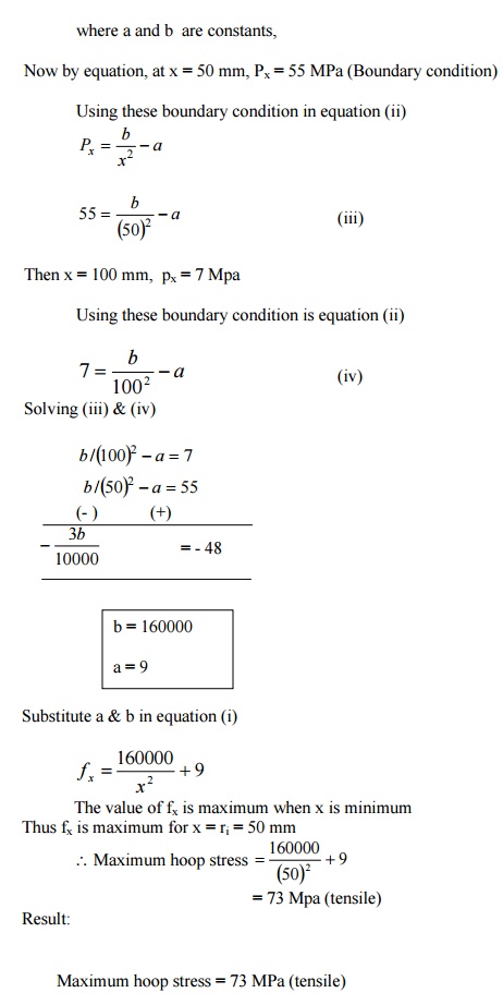
A thick steel cylinder having an internal
diameter of 100 mm an external diameter of 200
mm is subjected to an internal pressure of 55 M pa and an external
pressure of 7 Mpa. Find the maximum hoop
stress.
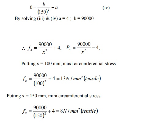
A
cast iron pipe has 200 mm internal diameter and 50 mm metal thickness. It
carries water under a pressure of 5 N/mm2.
Find the maximum and minimum intensities of
circumferential stress. Also sketch the distribution of circumferential
stress and
radial stress across the section.

Explain the stresses in compound thick
cylinders.
Solution:
Consider a compound thick cylinder as shown in
fig.
Let,
r1= Inner radius of the compound cylinder
r2=
Radius at the junction of the two cylinders
r3 = Outer radius of the compound cylinder
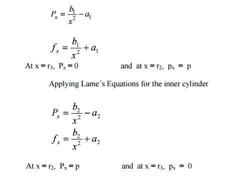
When one cylinder is shrunk over the other,
thinner cylinder is under compression and
the outer cylinder is under tension. Due to fluid pressure inside the
cylinder, hoop stress will develop. The
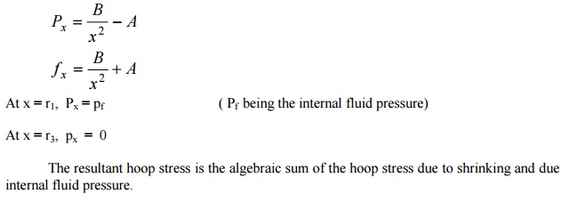
resultant hoop stress in the compound stress is that algebraic sum of the
hoop stress due to initial shrinkage and
that due to fluid pressure.
a. Stresses due to
initial shrinkage:
b. Stresses due to Internal fluid pressure.
To find the stress in the compound cylinder
due to internal fluid pressure alone, the inner and Equation,
A
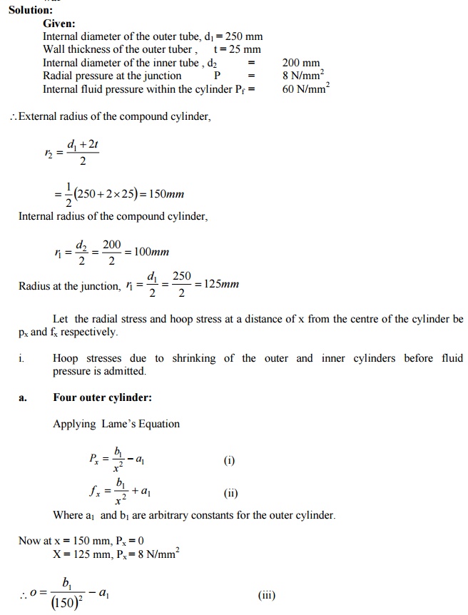
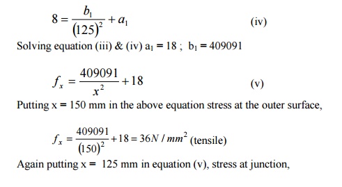
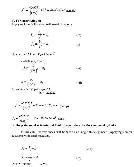
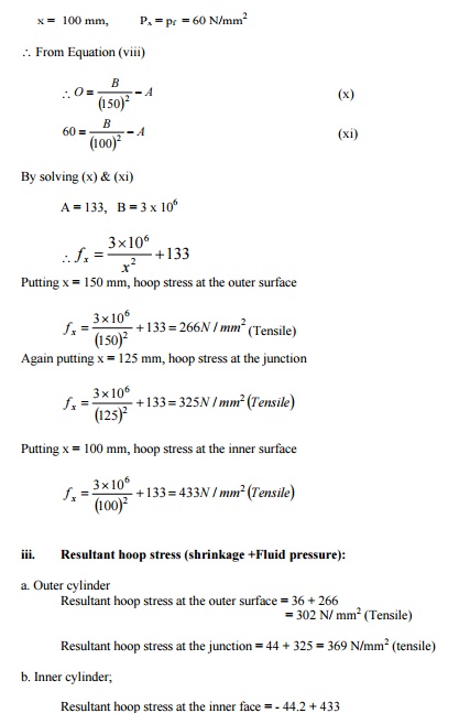
compound cylinder is composed of a tube of 250 mm internal diameter at 25 mm
wall thickness. It is shrunk on to a
tube of 200 mm internal diameter. The radial
pressure at the junction is 8 N/mm2.
Find the variation of hoop stress across
the wall of the compound cylinder, if it
is under an internal fluid pressure of 60 N/mm2
