Chapter: Measurements and Instrumentation : Transducers and Data Acquisition Systems
Analogue-To-Digital Converters
Analogue-To-Digital
Converters
Important
factors in the design of an analogue-to-digital converter are the speed of
conversion and the number of digital bits used to represent the analogue signal
level. The minimum number of bits used in analogue-to-digital converters is
eight.
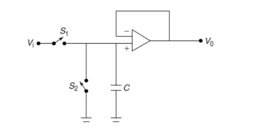
Operational
amplifier connected as ’sample and hold’ circuit
The use
of eight bits means that the
analogue signal can be represented to a resolution of 1 part in 256 if the input
signal is carefully scaled to make full use of the converter range. However, it
is more common to use either 10 bit or 12 bit analogue-to-digital converters,
which give resolutions respectively of 1 part in 1024 and 1 part in 4096.
Several types of analogue-to-digital converter exist. These differ in the
technique used to effect signal conversion, in operational speed, and in cost.
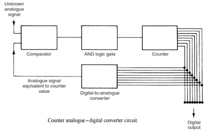
The
simplest type of analogue-to-digital converter is the counter analogue-to-digital converter, as shown in Figure 5.23.
This, like most types of analogue-to-digital
converter, does not convert continuously, but in a stop-start mode
triggered by special signals on the computer’s control bus. At the start of
each conversion cycle, the counter is set to zero. The digital counter value is
converted to an analogue signal by a digital- to-analogue converter (a
discussion of digital-to-analogue converters follows in the next section), and
a comparator then compares this analogue counter value with the unknown
analogue signal. The output of the comparator forms one of the inputs to an AND
logic gate. The other input to the AND gate is a sequence of clock pulses. The
comparator acts as a switch that can turn on and off the passage of pulses from
the clock through the AND gate. The output of the AND gate is connected to the
input of the digital counter. Following reset of the counter at the start of
the conversion cycle, clock pulses are applied continuously to the counter
through the AND gate, and the analogue signal at the output of the
digital-to-analogue converter gradually increases in magnitude. At some point
in time, this analogue signal becomes equal in magnitude to the unknown signal
at the input to the comparator. The output of the comparator changes state in
consequence, closing the AND gate and stopping further increments of the
counter. At this point, the value held in the counter is a digital
representation of the level of the unknown analogue signal.
Related Topics