Chapter: Pharmaceutical Drug Analysis: Amperometric Methods
Amperometric Methods: Instrumentation
INSTRUMENTATION
The amperometric titrations can be accomplished by any
one of the three methods, namely :
(i)
Amperometric titrations with the dropping mercury electrode,
(ii)
Amperometric titrations with a rotating platinum microelectrode, and
(iii)
Amperometric titrations with twin-polarized microelectrodes (or Biamperometric Titrations or Dead-stop-end-point method).
These three
techniques will be discussed in the sections that follow.
1. AMPEROMETRIC TITRATIONS WITH THE DROPPING MERCURY ELECTRODE
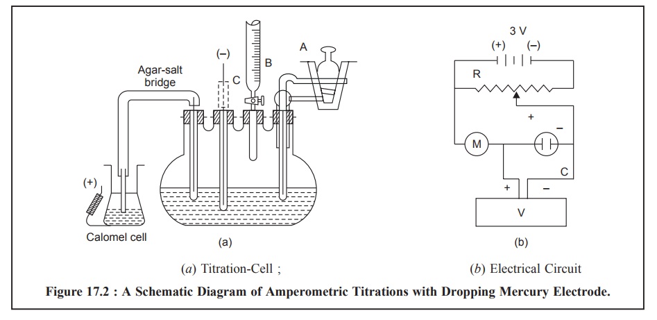
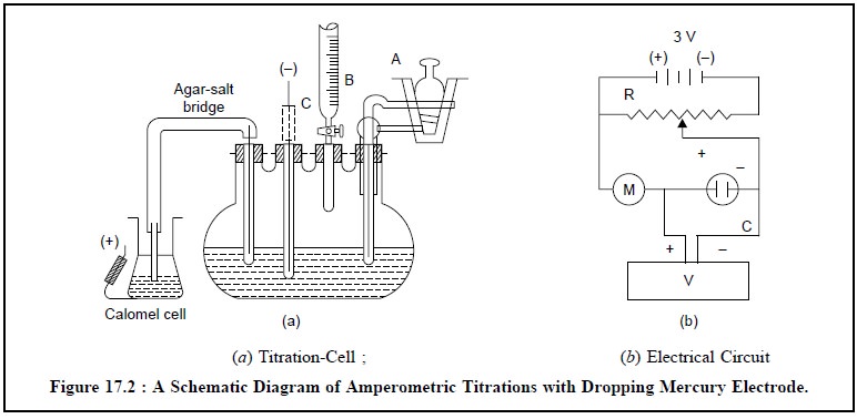
Figure 17.2 (a)
and (b) illustrates the schematic
diagram of amperometric titrations with the dropping mercury electrode having a
titration-cell and an electric circuit respectively.
The titration-cell Figure 17.2 (a) essentially comprises of a pyrex 100-ml, four-necked,
flat-bottomed flask. A semimicro burette (B) (graduated in 0.01 ml), a 2-way
gas-inlet tube (A) to enable N2 to pass either through the solution
or simply over its surface, a dropping mercury electrode (C) and an
agar-potassium salt-bridge* are duly fitted into the four necks with the help
of air-tight rubber stoppers.
The electrical circuit, Figure 17.2 (b), consists of two 1.5 V dry cells that provides a voltage applied
to the above titration cell. It is duly controlled and monitored by the
potential divider (R) and is conveniently measured with the help of a digital
voltmeter (V). Finally, the current flowing through the circuit may be read out
on the micro-ammeter (M) installed.

The following steps may be carried out in a sequential
manner for an amperometric titration, namely :
·
A known volume of the solution under investigation is
introduced in the titration cell,
·
The apparatus is assembled and electrical connections are
duly completed with dropping mercury electrode (C) as cathode and saturated
calomel half-cell as anode,
·
A slow stream of pure analytical grade N2 –
gas is bubbled through the solution for 15 minutes to get rid of dissolved O2
completely,
·
Applied voltage is adjusted to the desired value, and the
initial diffusion current (Id) is noted carefully,
·
A known volume of the reagent is introduced from the
semimicro burette (B), while N2 is again bubbled through the
solution for about 2 minutes to ensure thorough mixing as well as complete
elimination of traces of O2 from the added liquid,
·
The flow of N2 gas through the solution is
stopped, but is continued to be passed over the surface of the solution gently
so as to maintain an O2 free inert atmosphere in the reaction
vessel,
·
The current (µA) and microburette readings
are recorded simultaneously, and
·
Finally, the said procedure is repeated until sufficient
readings have been obtained to allow the equivalence point to be determined as
the intersection of the two linear portions of the graph thus achieved.
2. AMPEROMETRIC TITRATIONS WITH A ROTATING PLATINUM MICROELECTRODE
The rotating platinum microelectrode was first introduced
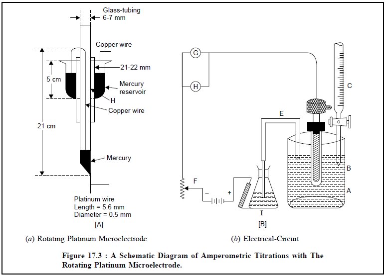
by Laitinen and Kolthoff in 1941. Figure 17.3 (a) depicts a simple rotating platinum microelectrode which is made
out from an usual standard ‘mer-cury seal’. A platinum wire (length : 5.0 mm ;
diameter : 0.5 mm) protrudes from the lower end wall of a 21 cm long 6 mm glass
tubing, which is bent at an angle of 90°. There are holes (H) in the stem of
the mercury reservoir for making electrical contact with it. The mercury
reservoir is provided with a flange fitted inward to prevent Hg from being
thrown out.
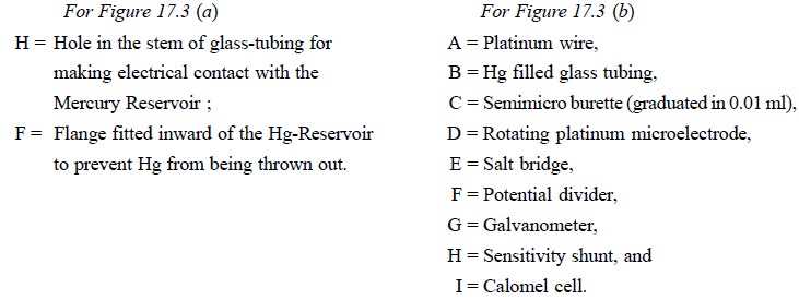
Figure 17.3 (b)
illustrates the electric circuit. The electrical connection is duly done to the
electrode by means of a strong amalgamated Cu-wire passing through the glass
tubing to the lower end of the Hg covering the sealed-in platinum wire ; the
upper end of which passes through a small hole made in the stem of the stirrer
and dips well into the Hg present in the Hg seal. Subsequently, a wire from the
Hg seal is connected to the source of applied voltage. The glass tubing serves
as the stem of the electrode that is rotated at a constant speed of 600 rpm.
3. AMPEROMETRIC TITRATIONS WITH TWIN-POLARIZED MICROELECTRODES (BIAMPEROMETRIC TITRATIONS OR DEAD-STOP-END-POINT METHOD)
Dead-stop-end-point method was first introduced by Foulk
and Bawden* in 1926. Evidently, this particular
technique is a modification of the classical amperometric titration. This
technique is specifically applicable to only such systems where the phenomenon
of oxidation-reduction exists both before as well as after the equivalence
point has been duly accomplished.
It essentially makes use of two identical, stationary
microelectrodes immersed in a well stirred solu-tion of the sample. A small
potential ranging between these electrodes ; and the resulting current is
measured subsequently as a function of the volume of reagent added. The
end-point is distinctly characterized by a sudden current rise from zero or a
decrease in the current to zero or a minimum at zero in a V-shaped curve.
Though this technique was first used in 1926, but it
received its due recognition only around 1950**. F
igure 17.4 represents a simple diagram of an amperometric
titration assembly with twin-polarized microelectrodes.
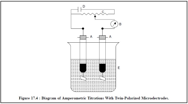
The various components are as follows :
A, A = Twin-polarized Platinum microelectrodes,
B= Micro-ammeter (µA),
C= 500 Ω,
0.5 watt potentiometer,
D = 3-Volt dry torch cell or a 2-volt accumulator
E = Reaction vessel.
The potentiometer is adjusted in such a fashion that
there is a distinct potential drop of about 80 to 100 millivolts between the
two platinum electrodes.
Related Topics