Chapter: Mechanical : Manufacturing Technology : CNC Machines
Types of NC systems
Types of NC systems
Machine controls are divided into three groups,
1.Traditional numerical control (NC);
2.Computer numerical control (CNC);
3.Distributed numerical control (DNC).
The original numerical control machines were referred to as NC
machine tool. They have
“hardwired” control,
whereby control is accomplished through the use of punched paper (or plastic)
tapes or cards. Tapes tend to wear, and become dirty, thus causing misreadings.
Many other problems arise from the use of NC tapes, for example the need to
manual reload the NC tapes for each new part and the lack of program editing
abilities, which increases the lead time. The end of NC tapes was the result of
two competing developments, CNC and DNC.
CNC refers to a system that has a
local computer to store all required numerical data. While CNC was used to
enhance tapes for a while, they eventually allowed the use of other storage
media, magnetic tapes and hard disks. The advantages of CNC systems include but
are not limited to the possibility to store and execute a number of large
programs (especially if a three or more dimensional machining of complex shapes
is considered), to allow editing of programs, to execute cycles of machining
commands, etc.
The development of CNC over many
years, along with the development of local area networking, has evolved in the
modern concept of DNC. Distributed numerical control is similar to CNC, except
a remote computer is used to control a number of machines. An off-site
mainframe host computer holds programs for all parts to be produced in the DNC
facility. Programs are downloaded from the mainframe computer, and then the
local controller feeds instructions to the hardwired NC machine.
The recent developments use a
central computer which communicates with local CNC computers (also called
Direct Numerical Control)
Controlled
axes
NC system can be classified on
the number of directions of motion they are capable to control simultaneously
on a machine tool. Each free body has six degree of freedom, three positive or
negative translations along x, y, and z-axis, and three rotations clockwise or
counter clockwise about these axes. Commercial NC systems are capable of
controlling simultaneously two, two and half, three, four and five degrees of
freedom, or axes. The NC systems which control three linear translations
(3-axis systems), or three linear translations and one rotation of the
worktable (4-axis systems) are the most common.
Although the directions of axes
for a particular machine tool are generally agreed as shown in the figure, the
coordinate system origin is individual for each part to be machined and has to
be decided in the very beginning of the process of CNC part programming.
Point-to-point
vs. continuous systems
The two major types of NC systems are (see the figure):
Point-to-point (PTP) system, and Contouring system.
PTP is a NC system, which
controls only the position of the components. In this system, the path of the
component motion relative to the workpiece is not controlled. The travelling
between different positions is performed at the traverse speed allowable for
the machine tool and following the shortest way.
Contouring NC systems are capable
of controlling not only the positions but also the component motion, i.e., the
travelling velocity and the programmed path between the desired positions.
Computer numerical control (CNC)
Numerical control (NC) is the
automation of machine tools that are operated by precisely programmed commands
encoded on a storage medium, as opposed to controlled manually via hand wheels
or levers, or mechanically automated via cams alone. Most NC today is computer
numerical control (CNC), in which computers play an integral part of the
control.
In modern
CNC systems, end-to-end component design is highly automated using
computer-aided design (CAD) and computer-aided manufacturing (CAM) programs.
The programs produce a computer file that is interpreted to extract the
commands needed to operate a particular machine via
a post processor, and then loaded into the CNC machines for production. Since any particular component might require
the use of a number of different tools – drills, saws, etc., modern machines often combine multiple
tools into a single "cell". In other installations, a number of
different machines are used with an external controller and human or robotic
operators that move the component from machine to machine. In either case, the
series of steps needed to produce any part is highly automated and produces a
part that closely matches the original CAD design.
The first NC machines were built
in the 1940s and 1950s, based on existing tools that were modified with motors
that moved the controls to follow points fed into the system on punched tape.
These early servomechanisms were rapidly augmented with analog and digital
computers, creating the modern CNC machine tools that have revolutionized the
machining processes.
Modern CNC mills differ little in
concept from the original model built at MIT in 1952. Mills typically consist
of a table that moves in the X and Y axes, and a tool spindle that moves in the
Z (depth). The position of the tool is driven by motors through a series of
step-down gears in order to provide highly accurate movements, or in modern
designs, direct-drive stepper motor or servo motors. Open-loop control works as
long as the forces are kept small enough and speeds are not too great. On
commercial metalworking machines closed loop controls are standard and required
in order to provide the accuracy, speed, and repeatability demanded.
As the controller hardware
evolved, the mills themselves also evolved. One change has been to enclose the
entire mechanism in a large box as a safety measure, often with additional
safety interlocks to ensure the operator is far enough from the working piece
for safe operation. Most new CNC systems built today are completely
electronically controlled.
CNC-like systems are now used for
any process that can be described as a series of movements and operations.
These include laser cutting, welding, friction stir welding, ultrasonic
welding, flame and plasma cutting, bending, spinning, hole-punching, pinning,
gluing, fabric cutting, sewing, tape and fiber placement, routing, picking and
placing (PnP), and sawing.
Mills
CNC mills use computer controls
to cut different materials. They are able to translate programs consisting of
specific number and letters to move the spindle to various locations and
depths. Many use G-code, which is a standardized programming language that many
CNC machines understand, while others use proprietary languages created by
their manufacturers. These proprietary languages while often simpler than
G-code are not transferable to other machines.
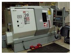
Lathes
Lathes are machines that cut
spinning pieces of metal. CNC lathes are able to make fast, precision cuts
using indexable tools and drills with complicated programs for parts that
normally cannot be cut on manual lathes. These machines often include 12 tool
holders and coolant pumps to cut down on tool wear. CNC lathes have similar
control specifications to CNC mills and can often read G-code as well as the
manufacturer's proprietary programming language.
Plasma cutters
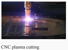
CNC plasma cutting
Plasma cutting involves cutting a
material using a plasma torch. It is commonly used to cut steel and other
metals, but can be used on a variety of materials. In this process, gas (such
as compressed air) is blown at high speed out of a nozzle; at the same time an
electrical arc is formed through that gas from the nozzle to the surface being
cut, turning some of that gas toplasma. The plasma is sufficiently hot to melt
the material being cut and moves sufficiently fast to blow molten metal away
from the cut.
Electric
discharge machining
Electric discharge machining
(EDM), sometimes colloquially also referred to as spark machining, spark
eroding, burning, die sinking, or wire erosion, is a manufacturing process in
which a desired shape is obtained using electrical discharges (sparks).
Material is removed from the workpiece by a series of rapidly recurring current
discharges between two electrodes, separated by a dielectric fluid and subject
to an electric voltage. One of the electrodes is called the tool-electrode, or
simply the "tool" or "electrode," while the other is called
the workpiece-electrode, or "workpiece."
When the distance between the two
electrodes is reduced, the intensity of the electric field in the space between
the electrodes becomes greater than the strength of the dielectric (at least in
some point(s)), which breaks, allowing current to flow between the two
electrodes. This phenomenon is the same as the breakdown of a capacitor. As a
result, material is removed from both the electrodes. Once the current flow
stops (or it is stopped – depending on the type of
generator), new liquid dielectric is usually conveyed into the inter-electrode
volume enabling the solid particles (debris) to be carried away and the
insulating proprieties of the dielectric to be restored. Adding new liquid
dielectric in the inter-electrode volume is commonly referred to as flushing.
Also, after a current flow, a difference of potential between the two
electrodes is restored to what it was before the breakdown, so that a new
liquid dielectric breakdown can occur.
Wire EDM
Also known as wire cutting EDM,
wire burning EDM, or traveling wire EDM, this process uses spark erosion to
machine or remove material with a traveling wire electrode from any
electrically conductive material. The wire electrode usually consists of brass
or zinc-coated brass material.
Sinker
EDM
Sinker
EDM, also called cavity type EDM or volume EDM, consists of an electrode and
workpiece submerged in an insulating liquid—often oil
but sometimes other dielectric fluids. The electrode and workpiece are
connected to a suitable power supply, which generates an
electrical potential between the two parts. As the electrode
approaches the workpiece, dielectric breakdown occurs in the fluid forming a
plasma channel) and a small spark jumps.
Water jet cutters
A water jet cutter, also known as a waterjet, is a tool capable
of slicing into metal or other materials (such as granite) by using a jet of
water at high velocity and pressure, or a mixture of water and an abrasive
substance, such as sand. It is often used during fabrication or manufacture of
parts for machinery and other devices. Waterjet is the preferred method when
the materials being cut are sensitive to the high temperatures generated by
other methods. It has found applications in a diverse number of industries from
mining to aerospace where it is used for operations such as cutting, shaping,
carving, and reaming.
Other CNC
tools: Many
other tools have CNC variants, including:
· Drills
· EDMs
· Embroidery
machines
· Lathes
· Milling
machines
· Wood
routers
· Sheet
metal works (Turret punch)
· Wire
bending machines
· Hot-wire
foam cutters
· Plasma
cutters
· Water jet
cutters
· Laser
cutting
· Oxy-fuel
· Surface
grinders
· Cylindrical
grinders
· 3D
Printing
· Induction
hardening machines
· submerged
welding
· knife
cutting
· glass
cutting
Related Topics