Chapter: Power System Operation and Control : Reactive Power -Voltage Control
Types of Excitation System
TYPES OF EXCITATION SYSTEM
Today, a large number of different types of exciter systems are used. Three main types can be distinguished:
DC excitation system,
where the exciter is a DC generator, often on the same axis as the rotor of the synchronous machine.
AC excitation system,
where the exciter is an AC machine with rectifier.
Static excitation system
where the exciting current is fed from a controlled rectifier that gets its power either directly from the generator terminals or from the power plant‟s auxiliary power system, normally containing batteries.
Ø In the latter case, the synchronous machine can be started against an unenergised net, “black start”. The batteries are usually charged from the net.
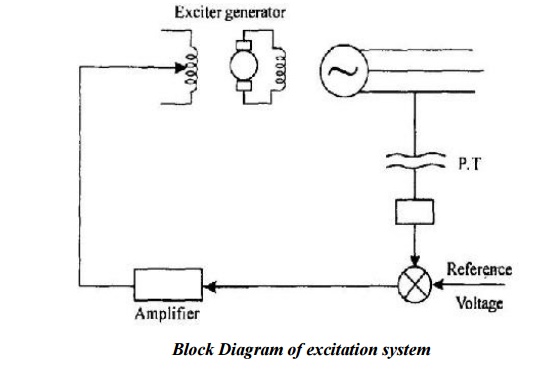
Block Schematic of Excitation Control:
Ø A typical excitation control system is shown in Fig.
Ø The terminal voltage of the alternator is sampled, rectified and compared with a reference voltage; the difference is amplified and fed back to the exciter field winding to change the excitation current.
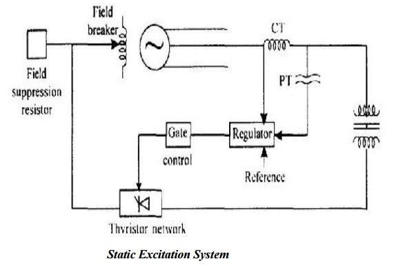
1. STATIC EXCITATION SYSTEM
Ø In the static excitation system, the generator field is fed from a thyristor network shown in Fig.
Ø It is just sufficient to adjust the thyristor firing angle to vary the excitation level.
Ø A major advantage of such a system is that, when required the field voltage can be varied through a full range of positive to negative values very rapidly with the ultimate benefit of generator Voltage regulation during transient disturbances.
Ø The thyristor network consists of either 3-phase fully controlled or semi controlled bridge rectifiers.
Ø Field suppression resistor dissipates Energy in the field circuit while the field breaker ensures field isolation during generator faults.
2. BRUSHLESS EXCITATION SCHEME
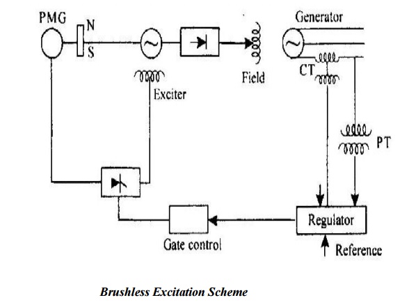
Ø In the brushless excitation system of an alternator with rotating armature and stationary field is employed as the main exciter.
Ø Direct voltage for the generator excitation is obtained by rectification through a rotating, semiconductor diode network which is mounted on the generator shaft itself.
Ø Thus, the excited armature, the diode network and the generator field are rigidly connected in series.
Ø The advantage of this method of excitation is that the moving contacts such as slip rings and brushes are completely eliminated thus offering smooth and maintenance-free operation.
Ø A permanent-magnet generator serves as the power source for the exciter field.
Ø The output of the permanent magnet generator is rectified with thyristor network and is applied to the exciter field.
Ø The voltage regulator measures the output or terminal voltage, compares it with a set reference and utilizes the error signal, if any, to control the gate pulses of the thyristor network.
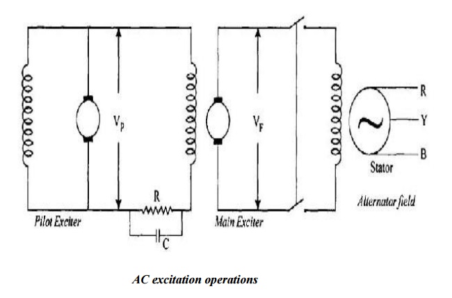
3. AC EXCITATION SYSTEM
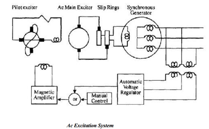
Exciter and Voltage Regulator:
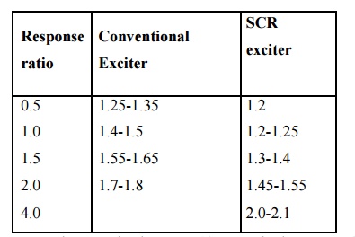
The function of an exciter is to increase the excitation current for voltage drop and decrease the same for voltage rise. The voltage change is defined
Where V1 is the terminal voltage and
Vref is the reference voltage.
Exciter ceiling voltage:
It is defined as the maximum voltage that may be attained by an exciter with specified conditions of load.
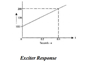
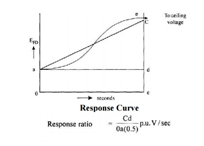
Exciter response:
It is the rate of increase or decrease of the exciter voltage. When a change in this voltage is demanded. As an example consider the response curve shown in Figure.
Exciter builds up:
Ø The exciter build up depends upon the field resistance and the charging of its value by cutting or adding.
Ø The greatest possible control effort is the complete shorting of the field rheostat when maximum current value is reached in the field circuit.
Ø This can be done by closing the contactor.
When the exciter is operated at rated speed at no load, the record of voltage as function of time with a step change that drives the exciter to its ceiling voltage is called the exciter build up curve. Such a response curve is show in Figure.4.14
Ø In general the present day practice is to use 125V excitation up to IOMVA units and 250V systems up to 100MVA units.
Ø Units generating power beyond IOOMVA have excitation system voltages variedly. Some use 350V and 375V system while some go up to 500V excitation system.
4. DC EXCITATION SYSTEM
Ø The excitation system of this category utilize dc generator as source of excitation power and provide current to the rotor of the synchronous machine through slip ring.
Ø The exciter may be driven by a motor or the shaft of the generator. It may be either self excited or separately excited.
Ø When separately excited, the exciter field is supplied by a pivot exciter comprising a permanent magnet generator.
Ø Below figure a simplified schematic representation of a typical dc excitation system. It consists of a dc commutator exciter which supplies direct current to the main generator field through slip ring.
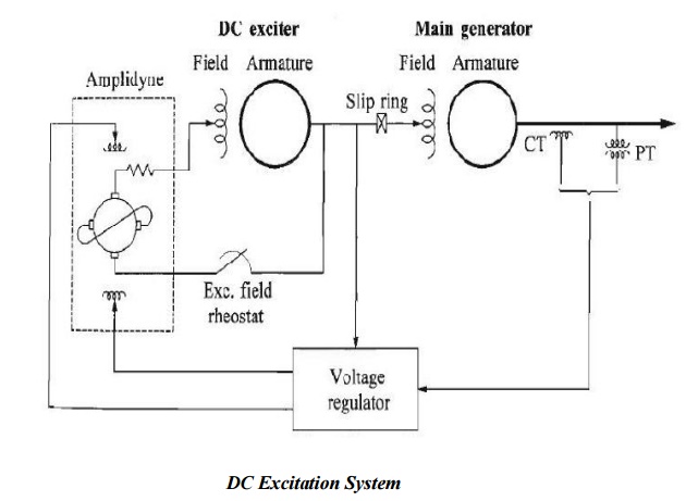
Ø Dc machine having two sets of brush 90 electrical degree apart, one set on its direct
(d) axis and the other set on its quadrature (q) axis.
Ø The control field winding is located on the d axis.
Ø A compensating winding in series with the d axis armature current, thereby cancelling negative feedback of the armature reaction.
Ø The brushes on the q axis are shorted, and very little control field power is required to produce a large current in the q axis armature.
Ø The q axis current is supplied mechanically by the motor.
5. MODELING OF EXCITATION SYSTEM
Ø Mathematical model of excitation system are essential for the assessment of desired performance requirement, for the design and coordination of supplementary control and protective circuits, and for system stability studies related to the planning and purpose of study.
Generator Voltage Control System
Ø The voltage of the generator is proportional to the speed and excitation (flux) of the generator.
Ø The speed being constant, the excitation is used to control the voltage.
Ø Therefore, the voltage control system is also called as excitation control system or automatic voltage regulator (AVR).
Ø For the alternators, the excitation is provided by a device (another machine or a static device) called exciter.
Ø For a large alternator the exciter may be required to supply a field current of as large as 6500A at 500V and hence the exciter is a fairly large machine.
Ø Depending on the way the dc supply is given to the field winding of the alternator
Ø (which is on the rotor), the exciters are classified as:
i) DC Exciters;
ii) AC Exciters; and
iii) Static Exciters.
Ø Accordingly, several standard block diagrams are developed by the IEEE working group to represent the excitation system.
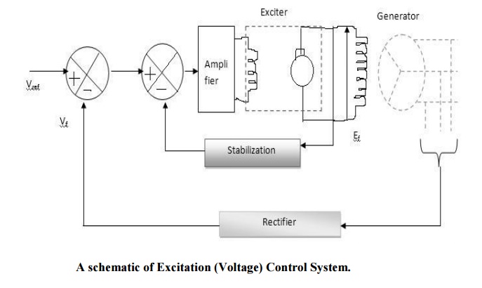
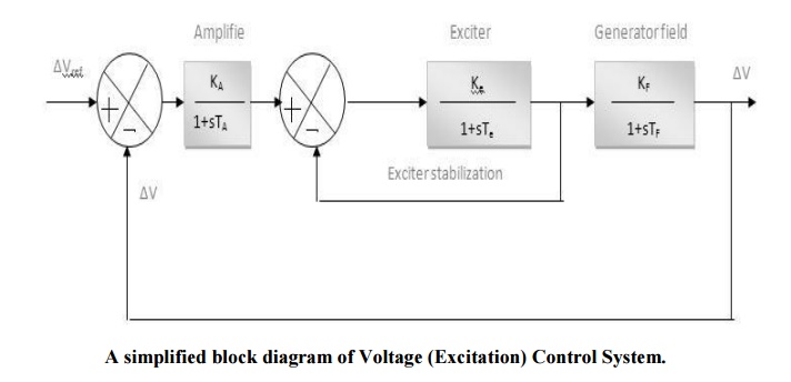
Ø A simplified block diagram of the generator voltage control system .
Ø The generator terminal voltage Vt is compared with a voltage reference Vref to obtain a voltage error signal ∆V.
Ø This signal is applied to the voltage regulator shown as a block with transfer function KA/ (1+TAs).
Ø The output of the regulator is then applied to exciter shown with a block of transfer function Ke/ (1+Tes).
Ø The output of the exciter Efd is then applied to the field winding which adjusts the generator terminal voltage.
Ø The generator field can be represented by a block with a transfer function KF/(1+sTF). The total transfer function
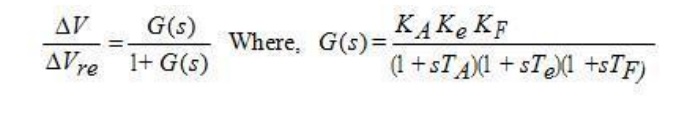
The stabilizing compensator shown in the diagram is used to improve the dynamic response of the exciter. The input to this block is the exciter voltage and the output is a stabilizing feedback signal to reduce the excessive overshoot.
Performance of AVR loop
Ø The purpose of the AVR loop is to maintain the generator terminal voltage within acceptable values.
Ø A static accuracy limit in percentage is specified for the AVR, so that the terminal voltage is maintained within that value.
Ø For example, if the accuracy limit is 4%, then the terminal voltage must be maintained within 4% of the base voltage.
Related Topics