Chapter: civil : Applied Hydraulic Engineering: Pumps
Reciprocating Pumps
Reciprocating Pumps
Introduction
There are two main types of pumps namely the dynamic and
positive displacement pumps. Dynamic pumps consist of centrifugal, axial and
mixed flow pumps. In these cases pressure is developed by the dynamic action of
the impeller on the fluid.
Momentum
is imparted to the fluid by dynamic action. This type was discussed in the
previous chapter. Positive displacement pumps consist of reciprocating and
rotary types. These types of pumps are discussed in this chapter. In these
types a certain volume of fluid is taken in an enclosed volume and then it is
forced out against pressure to the required application.
1 Comparison
Dynamic pumps
1. Simple in
construction.
2. Can
operate at high speed and hence compact.
3. Suitable
for large volumes of discharge at moderate pressures in a single stage.
4. Lower
maintenance requirements.
5. Delivery
is smooth and continuous.
Positive displacement
pumps
1. More
complex, consists of several moving parts.
2. Speed is
limited by the higher inertia of the moving parts and the fluid.
3. Suitable
for fairly low volumes of flow at high pressures.
4. Higher
maintenance cost.
5. Fluctuating
flow.
2.Description And Working
The main
components are:
1. Cylinder
with suitable valves at inlet and delivery.
2. Plunger
or piston with piston rings.
3. Connecting
rod and crank mechanism.
4. Suction
pipe with one way valve.
5. Delivery
pipe.
6. Supporting
frame.
7. Air vessels to reduce flow fluctuation and reduction of
acceleration head and friction head.
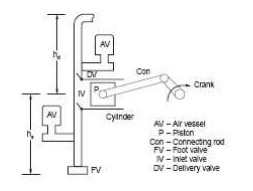
A
diagrammatic sketch is shown in Fig

The action is similar to that of reciprocating engines. As the
crank moves outwards, the piston moves out creating suction in the cylinder.
Due to the suction water/fluid is drawn into the cylinder through the inlet
valve. The delivery valve will be closed during this outward stroke.
During the return stroke as the fluid is incompressible
pressure will developed immediately which opens the delivery valve and closes
the inlet valve. During the return stroke fluid will be pushed out of the
cylinder against the delivery side pressure. The functions of the air vessels
will be discussed in a later section. The volume delivered per stroke will be
the product of the piston area and the stroke length.
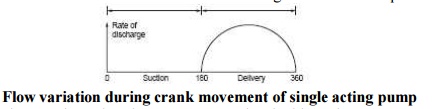
In a single acting type of pump there will be only one
delivery stroke per revolution. Suction takes place during half revolution and
delivery takes place during the other half. As the piston speed is not uniform
(crank speed is uniform) the discharge will vary with the position of the
crank. The discharge variation is shown in figure.
In a
single acting pump the flow will be fluctuating because of this operation.
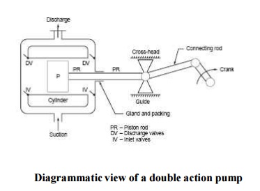
Fluctuation can be reduced to some extent by double acting
pump or multicylinder pump. The diagrammatic sketch of a double acting pump is
shown in figure In this case the piston cannot be connected directly with the
connecting rod.
A gland and packing and piston rod and cross- head and guide
are additional components. There will be nearly double the discharge per
revolution as compared to single acting pump.When one side of the piston is
under suction the other side will be delivering the fluid under pressure. As
can be noted, the construction is more complex
.
3.Flow Rate and Power
Theoretical
flow rate per second for single acting pump is given by,
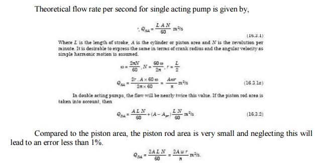
Compared to the piston area, the piston rod area is very small
and neglecting this will lead to an error less than 1%.
4.Slip
There can
be leakage along the valves, piston rings, gland and packing which will reduce
the discharge to some extent. This is accounted for by the term slip.
Percentage
o Slip = Qa -Qn / Qa x 100
Where Qth is the
theoretical discharge given by equation and Qac is the measured
discharge. If actual discharge is greater than theoretical discharge negative
value is found
this negative
value is called negative slip.
5.Coefficient
of discharge
It has
been found in some cases that Qac > Qth, due to operating
conditions. In this case the slip is called negative slip. When the delivery
pipe is short or the delivery head is small and the accelerating head in the
suction side is high, the delivery valve is found to open before the end of
suction stroke and the water passes directly into the delivery pipe. Such a
situation leads to negative slip.
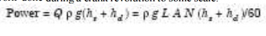
Theoretical power = mg(hs + hd ) W
where m is given by Q � ?.
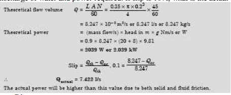
Problem.1
A
single acting reciprocating pump has a bore of 200 mm and a stroke of 350 mm
and runs at 45 rpm. The suction head is 8 m and the delivery head is 20 m.
Determine the theoretical discharge of water and power required. If slip is
10%, what is the actual flow rate ?
6.Indicator Diagram
The
pressure variation in the cylinder during a cycle consisting of one revolution
of the crank. When represented in a diagram is termed as indicator diagram. The
same is shown in figure.
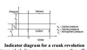
Figure represents an ideal diagram, assuming no other effects
are involved except the suction and delivery pressures. Modifications due to
other effects will be discussed later in the section. Point 1 represents the
condition as the piston has just started moving during the suction stroke.
1-2
represents the suction stroke and the pressure in the cylinder is the suction
pressure below the atmospheric pressure. The point 3 represents the condition
just as the piston has started moving
when the pressure increases to the delivery
pressure. Along 3-4 representing
the delivery stroke the pressure
remains constant. The
area enclosed represents the work done during a crank
revolution to some scale.
7.Acceleration Head
The piston in the reciprocating pump has to move from rest
when it starts the suction stroke. Hence it has to accelerate. The water in the
suction pipe which is also not flowing at this point has to be accelerated.
Such acceleration results in a force which when divided by area results as
pressure.
When the
piston passes the mid point, the velocity gets reduced and so there is
retardation of the piston together with the water in the cylinder and the pipe.
This again results in a pressure. These pressures are called acceleration
pressure and is denoted as head of fluid (h = P/?g) for
convenience.
Referring
to the figure shown below the following equations are written.
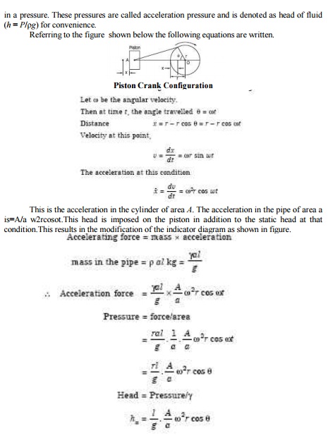
This is
the acceleration in the cylinder of area A. The acceleration in the pipe
of area a is=A/a w2rcosot.This head is imposed on the piston in addition to the
static head at that condition.This results in the modification of the indicator
diagram as shown in figure.
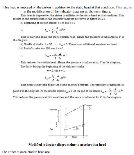
The effect of acceleration
head are:
No change in the work done. pressure at 1?is around
2.5 m of head of water (absolute). Which is directly related to speed, the
speed of operation of reciprocating pumps is limited. Later it will be shown
than the installation of an air vessel alleviates this problem to some extent.
8.Work done by the Pump
For
single acting
W=
?gALN(hs+hd+0.67hfs+0.67hfd)/60
For
Double acting
W=2?gALN(hs+hd+0.67hfs+0.67hfd)/60
Where
hfs, hfd =loss of head due to acceleration in the suction and delivery Pipe.
Related Topics