Chapter: Flexible Alternating Current Transmission System : Emerging FACTS Controllers
Principle of Operation and Advantages- STATCOM
PRINCIPLE OF OPERATION
Ø A STATCOM
is a controlled reactive-power source. It provides the desired reactive-power
generation and absorption entirely by means of electronic processing of the
voltage and current waveforms in a voltage-source converter (VSC).
Ø A
single-line STATCOM power circuit is shown in Fig.(a),where a VSC is connected
to a utility bus through magnetic coupling.
Ø In Fig.
(b), a STATCOM is seen as an adjustable voltage source behind a reactance
meaning that capacitor banks and shunt reactors are not needed for
reactive-power generation and absorption, thereby giving a STATCOM a compact
design, or small footprint, as well as low noise and low magnetic impact.
Ø The
exchange of reactive power between the converter and the ac system can be
controlled by varying the amplitude of the 3-phase output voltage, Es, of the converter, as illustrated in
Fig. (c).
Ø If the
amplitude of the output voltage is increased above that of the utility bus
voltage, Et, then a current flows
through the reactance from the converter to the ac system and the converter
generates capacitive-reactive power for the ac system.
Ø If the
amplitude of the output voltage is decreased below the utility bus voltage,
then the current flows from the ac system to the converter and the converter
absorbs inductive-reactive power from the ac system.
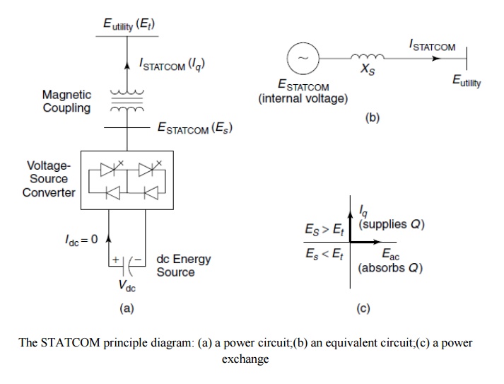
The STATCOM principle diagram: (a) a power
circuit;(b) an equivalent circuit;(c) a power exchange
Ø If the
output voltage equals the ac system voltage, the reactive-power exchange
becomes zero, in which case the STATCOM is said to be in a floating state.
Ø Adjusting
the phase shift between the converter-output voltage and the acsystem voltage
can similarly control real-power exchange between the converter and the ac
system. In other words, the converter can supply real power to the ac system
from its dc energy storage if the converter-output voltage is made to lead the
ac-system voltage.
Ø On the
other hand, it can absorb real power from the ac system for the dc system if
its voltage lags behind the ac-system voltage.
Ø A STATCOM
provides the desired reactive power by exchanging the instantaneous reactive
power among the phases of the ac system.
Ø The
mechanism by which the converter internally generates and/ or absorbs the
reactive power can be understood by considering the relationship between the
output and input powers of the converter. The converter switches connect the
dc-input circuit directly to the ac-output circuit. Thus the net instantaneous
power at the acoutput terminals must always be equal to the net instantaneous
power at the dc-input terminals (neglecting losses).
Ø Assume
that the converter is operated to supply reactive-output power. In this case,
the real power provided by the dc source as input to the converter must be
zero.
Ø Furthermore,
because the reactive power at zero frequency (dc) is by definition zero, the dc
source supplies no reactive ower as input to the converter and thus clearly
plays no part in the generation of reactive-output power by the converter.
Ø In other
words, the converter simply interconnects the three output terminals so that
the reactive-output currents can flow freely among them. If the terminals of
the ac system are regarded in this context, the converter establishes a
circulating reactive-power exchange among the phases. However, the real power
that the converter exchanges at its ac terminals with the ac system must, of
course, be supplied to or absorbed from its dc terminals by the dc capacitor.
Ø Although
reactive power is generated internally by the action of converter switches, a
dc capacitor must still be connected across the input terminals of the
converter.
Ø The
primary need for the capacitor is to provide a circulating-current path as well
as a voltage source.
Ø The
magnitude of the capacitor is chosen so that the dc voltage across its
terminals remains fairly constant to prevent it from contributing to the
ripples in the dc current. The VSC-output voltage is in the form of a staircase
wave into which smooth sinusoidal current from the ac system is drawn,
resulting in slight fluctuations in the output power of the converter.
Ø However,
to not violate the instantaneous power-equality constraint at its input and
output terminals, the converter must draw a fluctuating current from its dc
source.
Ø Depending
on the converter configuration employed, it is possible to calculate the
minimum capacitance required to meet the system requirements, such as ripple
limits on the dc voltage and the rated-reactivepower support needed by the ac
system.
Ø The VSC
has the same rated-current capability when it operates with the capacitive- or
inductive-reactive current.
Ø Therefore,
a VSC having a certain MVA rating gives the STATCOM twice the dynamic range in
MVAR (this also contributes to a compact design). A dc capacitor bank is used
to support (stabilize) the controlled dc voltage needed for the operation of
the VSC.
Ø The
reactive power of a STATCOM is produced by means of power-electronic equipment
of the voltage-source-converter type.
Ø The VSC may be a 2- level or 3-level type, depending on the required output power and voltage . A number of VSCs are combined in a multi-pulse connection to form the STATCOM.
In the
steady state, the VSCs operate with fundamental-frequency switching to minimize
converter losses. However, during transient conditions caused by line faults, a
pulse width–modulated (PWM) mode is used to prevent the fault current from
entering the VSCs . In this way, the STATCOM is able to withstand transients on
the ac side without blocking.
Advantages of STATCOM
1. It
occupies a small footprint, for it replaces passive banks of circuit elements
by compact electronic converters;
2. It offers
modular, factory-built equipment, thereby reducing site work and commissioning
time; and
3. It uses
encapsulated electronic converters, thereby minimizing its environmental
impact.
Related Topics