Chapter: Solid State Drives : Synchronous Motor Drives
Power Factor Correction of Permanent Magnet Synchronous Motor Drive
Power Factor Correction Of Permanent Magnet Synchronous Motor Drive With Field Oriented Control Using Space Vector Modulation
Field oriented control demonstrates that, a synchronous motor could be controlled like a separately excited dc motor by the orientation of the stator mmf or current vector in relation to the rotor flux to achieve a desired objective. The aim of the FOC method is to control the magnetic field and torque by controlling the d and q components of the stator currents or relatively fluxe. With the information of the stator currents and the rotor angle a FOC technique can control the motor torque and the flux in a very effective way.
The main advantages of this technique are the fast response and reduced torque ripple. The implementation of this technique will be carried out using two current regulators, one for the direct-axis component and another for the quadrature -axis component, and one speed regulator. There are three PI regulators in the control system. One is for the mechanical system (speed) and two others for the electrical system (d and q currents). At first, the reference speed is compared with the measured speed and the error signal is fed to the speed PI controller.
This regulator compares the actual and reference speed and outputs a torque command. Once is
obtained the torque command, it can be turned into the quadrature-axis current reference, Iq,ref . There is a PI controller to regulate the d component of the stator current. The reference value, Id,ref, is zero since there is no flux weakening operation. The d component error of the current is used as an input for the PI regulator.
Moreover, there is another PI controller to regulate the q component of the current. The reference value is compared with the measured and then fed to the PI regulator. The performance of the FOC block diagram can be summarized in the following steps
The performance of the FOC block diagram can be summarized in the following steps:
1. The stator currents are measured as well as the rotor angle.
2. The stator currents are converted into a two-axis reference frame with the Clark Transformation.
3. The α,β currents are converted into a rotor reference frame using Park Transformation
4. With the speed regulator, a quadrature-axis current reference is obtained. The d-current controls the air gap flux, the q-current control the torque production.
5. The current error signals are used in controllers to generate reference voltages for the inverter.
6. The voltage references are turned back into abc domain.
7. With these values are computed the PWM signals required for driving the inverter.
SPACE VECTOR MODULATION
The basis of SVPWM is different from that of sine pulse width modulation (SPWM). SPWM aims to achieve symmetrical 3-phase sine voltage waveforms of adjustable voltage and frequency, while SVPWM takes the inverter and motor as a whole, using the eight fundamental voltage vectors to realize variable frequency of voltage and speed adjustment. SVPWM aims to generate a voltage vector that is close to the reference circle through the various switching modes of inverter. Fig is the typical diagram of a three-phase voltage source inverter model. For the on- off state of the three-phase inverter circuit, every phase can be considered as a switch S. Here, SA(t), SB(t) and SC(t) are used as the switching functions for the three phases, respectively.
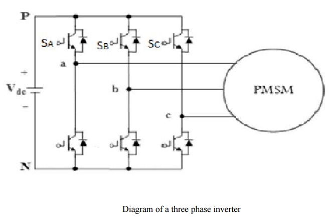
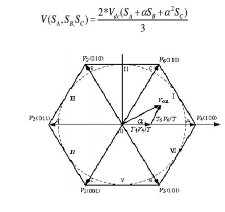
The space vector of output voltage of inverter can be expressed as
PMSM Drive with Active Power Factor Correction (Apfc):
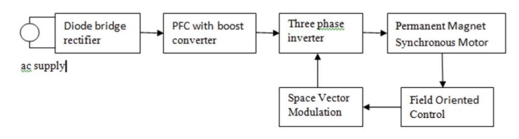
PMSM drive with PFC
The above figure shows the block diagram of PMSM drive with Active power Factor Correction. The APFC consists of an energy stored element, switching device and control module. It is commonly installed between the power rectifier and the dc link bus. The main purpose of APFC is to make the input of the power supply look like a pure resistor. In other words, it is to make the input current waveform in phase with the input voltage waveform so that there is no phase displacement between them. The operation of APFC is basically based on a controller that can output the signal to a switching device to control the energy being stored or released in the reactive elements. In such a way, the input current waveform can be adjusted. The magnitude and phase of the input current waveforms by proper control can follow that of the input voltage waveform. Consequently, the power factor improvement can be achieved and further, the voltage stability can be obtained as well. The dc link voltage for the inverter is obtained from PFC block. The stator currents and rotor position of PMSM are given to the FOC, which controls the flux and torque components.
The current error signals are used in controllers to generate reference voltages Vα and Vβ, which are the inputs of SVM. Space Vector modulation gives signals required for driving the inverter. By using inverter three phase supply is given to the PMSM
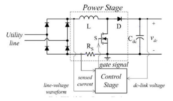
PFC with Boost Converter Circuit
The above Figure shows the circuit of power factor correction circuit with boost converter. An uncontrolled diode rectifier with a boost converter is used to convert the single phase AC voltage into a constant DC link voltage, which is fed to the three phase inverter supplying a PMSM.
The boost converter is the widely used topology for achieving power factor correction. This converter draws nearly unity power factor current from the AC mains and eliminates a harmonic current which regulates the DC link voltage even under fluctuating voltage conditions of AC mains.
This circuit uses a diode bridge rectifier, an inductor which is connected in series with the supply, a switch MOSFET and an output capacitor. The bulk energy storage capacitor sits on the output side of the converter rather than just after the diode rectifier bridge. The average inductor current which charges the bulk capacitor is proportional to the utility line voltage.
For proper operation, the output voltage must be higher than the peak line voltage and current drawn from the line must be proportional to the line voltage. In circuit operation, it is assumed that the inductance of boost inductor is large so that it can be represented by constant current source and that the output ripple voltage is negligible so that the voltage across the output filter capacitor can be represented by constant voltage source.
Related Topics