Chapter: Flexible Alternating Current Transmission System : Introduction
Overview of FACTS Devices
OVERVIEW OF FACTS DEVICES
1. SVC – Static Var Compensator
Ø A SVC is
an electrical device for providing fast acting reactive power on high-voltage
electricity transmission networks.
Ø SVCs are
part of the FACTS device family and regulating voltage and stabilizing the
system.
Ø
Unlike a synchronous condenser which is a rotating
electrical machine a SVC has no significant moving parts and prior to the invention of the
SVC power factor compensation was
the preserve of large rotating machines such as synchronous condensers or
switched capacitor banks.
Ø The SVC
is an automated impedance matching device designed to bring the system closer
to unity power factor.
Ø SVCs are
used in two main situations:
o Connected to the power system, to regulate the
transmission voltage.
o
Connected near large industrial loads, to improve
power quality.
Ø In
transmission applications the SVC is used to regulate the grid voltage.
Ø If the
power system’s reactive load is capacitive (leading) the SVC will use thyristor
controlled reactors to consume vars from the system lowering the system
voltage.
Ø Under
inductive (lagging)conditions the capacitor banks are automatically switched on
thus providing a higher system voltage and by connecting the
thyristor-controlled reactor which is continuously variable along with a
capacitor bank step and the net result is continuously-variable leading or
lagging power.
Ø In
industrial applications SVCs are typically placed near high and rapidly varying
loads such as arc furnaces where they can smooth flicker voltage.
Description:
Typically
an SVC comprises one or more banks of fixed or switched shunt capacitors or
reactors of which atleast one bank is switched by thyristors.
The elements which may be used to make an SVC typically include:
Thyristor Controlled Reactor (TCR) where the reactor may be air or iron cored.
Thyristor
Switched Capacitor (TSC).
Harmonic filter(s).
Mechanically switched capacitors or reactors.
Connection:
Ø Generally
SVC is not done at line voltage; a bank of transformers steps the transmission
voltage down to a much lower level.
Ø This
reduces the size and number of components needed in the SVC although the
conductors must be very large to handle high currents associated with the lower
voltage.
Ø In some
SVC for industrial applications such as electric arc furnaces where there may
be an existing medium-voltage bus bar present the SVC may be directly connected
in order to save the cost of the transformer.
Ø The
dynamic nature of the SVC lies in the use of thyristors connected in series and
inverse-parallel forming “thyristor valves” and the disc-shaped semiconductors
usually several inches in diameter are usually located indoors in a “valve
house”.
Advantages:
Ø Near
instantaneous response to changes in the system voltage. For this reason they
are often operated at close to their zero-point in order to maximize the
reactive power correction they can rapidly provide when required.
Ø In
general, cheaper, higher-capacity, faster and more reliable than dynamic
compensation schemes such as synchronous condensers.
2. Thyristor Controlled Series
Capacitor (TCSC)
Ø TCSC is a
power electronic based system and Thyristor Switched Capacitor is connected in
series with a bidirectional thyristor valve.
Ø The TCSC
can control power flow, mitigate sub-synchronous resonance, improve transient
stability, damp out power system oscillations resulting increase of power
transfer capability.
Ø A single
diagram of TCSC shows two modules connected in series and there can be one or
more module depending on the requirement to reduce the costs and TCSC may be
used in conjunction with fixed series capacitors.
Ø Nowadays
TCSC is being included in some of the transmission systems and the basic
circuit of a TCSC in one of the phase is shown in the fig.controls the current
through the reactor.
Ø The
forward-looking thyristor has firing angle 900 – 1800 and
firing the thyristors at this time results in a current flow through the
inductor that is opposite to the capacitor current and in this loop current
increases the voltage across the capacitor.
Ø Further
the loop current increases as firing angle decreases from 1800.
Ø The
different compensation levels are obtained by varying the firing angle of the
reactor-circuit-thyristor.
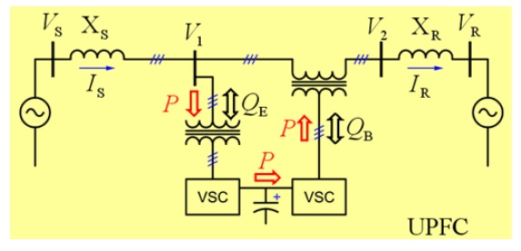
3. UNIFIED POWER FLOW CONTROLLER
(UPFC)
Ø The UPFC
is the most versatile member of FACTS family using power electronics to control
power flow on power grids.
Ø The UPFC
uses a combination of a shunt controller (STATCOM) and a series controller
(SSSC) interconnected through a common DC bus.
P = (V2V3 sinᵟ)/X and Q
= (V2(V2 – V3 cosᵟ))/X
Ø This
FACTS topology provides much more flexibility than the SSSC for controlling the
line active and reactive power because active power can now be transferred from
the shunt converter to the series converter through the DC bus.
4. INTEGRAL POWER FLOW CONTROLLER
(IPFC)
Ø In other
FACTS controllers there are two or more VSCs coupled together via a common DC
bus which increases not only the controllability but also the complexity.
Ø For UPFC
the connection between the shunt VSC and series VSC allows active power
exchange of the two VSCs so the series VSC can control both the line active and
reactive power flow.
Ø The shunt
VSC regulates the bus voltage and satisfies the balance of power circulation
through the DC capacitor.
Ø For IPFC
two series VSCs connect to each other at the DC bus so one of them (assumed as
the Master VSC) can control both line active and reactive power and the other
one (assumed as Slave VSC) can only regulate line active power supporting sufficient
active power to the Master VSC through the DC tie.
Related Topics