Chapter: Transmission Lines and Waveguides : High Frequency Transmission Lines
Line of Zero Dissipation, Voltage and Current on the Dissipation
LINE OF ZERO DISSIPATION, VOLTAGE AND CURRENT ON THE DISSIPATION
Fundamental electrical parameters
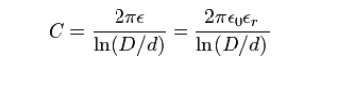
Shunt capacitance per unit length, in farads per metre.
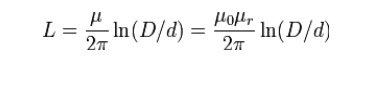
Series inductance per unit length, in henrys per metre.
Series resistance per unit length, in ohms per metre. The resistance per unit length is just the resistance of inner conductor and the shield at low frequencies. At higher frequencies, skin effect increases the effective resistance by confining the conduction to a thin layer of each conductor.
Shunt conductance per unit length, in siemens per metre. The shunt conductance is usually very small because insulators with good dielectric properties are used (a very low loss tangent). At high frequencies, a dielectric can have a significant resistive loss.
Derived electrical parameters
* Characteristic impedance in ohms (Ω). Neglecting resistance per unit length for most coaxial cables, the characteristic impedance is determined from the capacitance per unit length (C) and the inductance per unit length (L). Those parameters are determined from the ratio of the inner (d) and outer (D) diameters and the dielectric constant (ε). The characteristic impedance is given by[3]
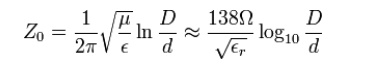
Assuming the dielectric properties of the material inside the cable do not vary appreciably over the operating range of the cable, this impedance is frequency independent above about five times the shield cutoff frequency. For typical coaxial cables, the shield cutoff frequency is 600 (RG-6A) to 2,000 Hz (RG-58C)
Attenuation (loss) per unit length, in decibels per meter. This is dependent on the loss in the dielectric material filling the cable, and resistive losses in the center conductor and outer shield. These losses are frequency dependent, the losses becoming higher as the frequency increases. Skin effect losses in the conductors can be reduced by increasing the diameter of the cable.
A cable with twice the diameter will have half the skin effect resistance. Ignoring dielectric and other losses, the larger cable would halve the dB/meter loss. In designing a system, engineers consider not only the loss in the cable, but also the loss in the connectors.
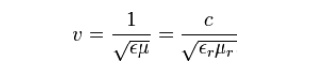
Velocity of propagation, in meters per second. The velocity of propagation depends on the dielectric constant and permeability (which is usually 1).
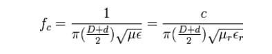
Cutoff frequency is determined by the possibility of exciting other propagation modes in the coaxial cable. The average circumference of the insulator is π(D + d) / 2. Make that length equal to 1 wavelength in the dielectric. The TE01 cutoff frequency is therefore
Related Topics