Chapter: Civil : Railway Airport Harbour Engineering : Railway Engineering : Construction of New Railway Lines and Track Linking
Construction of New Railway Lines
Introduction
The construction of a new railway
line in an area is normally required for one or more of the following reasons.
(a) Strategic
and political considerations
(b) Development
of backward areas
(c) Connecting
new trade centres
(d) Shortening
existing rail lines
Existing single railway lines are
also doubled in a few cases to cope with the burden of additional traffic.
Recently, a large number of projects have been undertaken for converting
existing metre gauge lines into broad gauge lines in order to ensure a uniform
gauge for the smooth flow of traffic.
Construction of New Lines
The main tasks involved in the construction of a new line are
as follows.
(a) Land
acquisition
(b) Earthwork
and bridges
(c) Construction
of station building, staff quarters, and other allied facilities, including
platforms and sheds
(d) Laying of
plates including ballasting of track
(e) Opening
of section to traffic
1 Land Acquisition
The work of land acquisition
should start well in advance so that all the legal and financial formalities
are completed in time and the possession of the land is taken for starting
construction work. Land acquisition is done with the help of the State
Government as per the procedure laid down in the Land Acquisition Act.
Normally Sections 4 and 6 of the
Land Acquisition Act are applied for the acquisition of land. Whenever land is
to be acquired, it is generally done after giving a certain notice and paying
the requisite compensation. In the case of an emergency, land can also be
acquired urgently by the application of Special Sections 9 and 17 of the Land
Acquisition Act.
The land being acquired should be
sufficient for the formation, berm, and borrow pits. It should also have
adequate provision for any future expansion. Even when a single line is to be
constructed, it should be ascertained that the land made available is suitable
for future conversion into a double line. Normally a strip of 15 to 25 m of
land is acquired for the construction of a railway line. An extra width of land
is acquired for station yards. In the case of small stations, the width
normally adopted is 150 � 1000 m.
The minimum measurements of the
selected land should be such that it can cater to the following requirement.
Width of formation The land
should be adequate so as to accommodate the width of the formation.
Side slope This
depends on the nature of the soil and is normally taken as 2:1 (horizontal:vertical).
Width of berm
The width of the berm is usually kept as 3 m.
Borrow pits If the
land is not very costly, adequate land should also be made available for
borrow pits. Borrow pits may be provided on one side of the track for low banks
and on both sides of the track for medium and high banks.
When the land is expensive,
borrow pits need not be provided and instead earth can be borrowed from
adjoining areas. Extra land is, however, required for station yards, level
crossings, and bridge approaches.
2 Earthwork for Formation
Depending upon the rail level and
general contour of the area, the formation may be laid in an embankment or in a
cutting. A formation laid in an embankment is normally preferred because it
affords good drainage. The height of the embankment also depends on the high
flood level (HFL) of the area and a reasonable free board should be given above
the HFL.
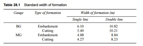
The
standard widths of the formation for BG and MG lines are given in Table 28.1
Table 28.1 Standard width of
formation
Some of
the points to be kept in mind with regard to earthwork are given below.
(a) Earthwork
is normally done in 30-cm layers so that the soil is well compacted.
(b) Mechanical
compaction is normally done after each layer of earthwork with the help of a
sheep foot roller to obtain 90% maximum dry density at an optimum moisture
content.
(c) A
shrinkage allowance of 5% is made for the consolidation of the final cross
section in the case of mechanical compaction. The shrinkage allowance is
increased to 10% if no mechanical compaction is involved.
(d) A blanket
of a thickness of about 30 cm is provided at the top of the embankment where
the soil is not of good quality.
(e) In areas
where there are both cuttings and embankments, the soil from the cuttings
should be used for the embankments up to an economical lead. The economical
limit of moving the earth in the longitudinal direction is determined by the mass-haul
curve.
(f) For the
early execution of earthwork, the section is normally divided into convenient
zones, with each zone requiring earthwork costing Rs 1.5 to 3 million
approximately. Tenders are separately invited for each zone so that work can
progress simultaneously in all the zones.
3. Bridges
Bridges should be designed to bear the load of the heaviest
locomotive likely to pass the section. Depending upon the topography of the
location and the type of stream to be crossed, hume pipe culverts, RCC slab
bridges, plate girders, PRC girder bridges, or steel bridges are designed.
Bridges, being important structures, are normally constructed to accommodate a
double line even in those sections where only a single line is being set up so
that future expansions can be planned.
Separate tenders are invited for the construction
of important bridges so that the bridge design and construction can also be
included in the tender documents. Minor bridges and culverts are normally
included in the earthwork zones mentioned earlier.
4
Service Buildings and Staff Quarters
Service buildings include buildings such as the station
master's office or telegraph office, which are basically required for providing
assistance in the running of trains. Apart from this, staff quarters and other
passenger amenities such as platforms, foot over bridges, waiting halls, and
retiring rooms are also provided at the stations. Many other ancillary
facilities such as water, drainage, telephone lines, and electricity are also
made available at every station.
All these constructions are taken up
simultaneously by civil engineers, electrical engineers, and signal engineers
so that all work can progress together.
5 Plate Laying or Track Linking
Once the formation is ready, plate laying or track linking
should be done, which basically consists of laying rails, sleepers, and
fastenings. The following methods can be adopted for plate laying.
Tram line method
In this method, a temporary line
known as a tram line is laid by the side of the proposed track for
transporting track material to the site. This method can be useful in flat
terrains, where laying of a tram line on the natural ground may be
comparatively easier. This method is, however, seldom used in actual practice.
A modification of the above
method, called side method, is also in practice, where track and bridge
material such as steel girders and RCC slabs is carried to the site in trucks
on a service road that runs parallel to the track. These materials are then
unloaded near the work site. This method is used only in cases where the
terrain is comparatively flat.
American method
In this method, rails and
sleepers are first assembled in the base depot, and the pre-assembled track
panels are then conveyed to the site along with the necessary cranes, etc. The
track panels are then unloaded at the site of work either manually or with the
help of cranes and laid in their final position.
This procedure is used in many
developed countries, particularly where concrete sleepers are laid, which are
quite heavy and not very easy to handle manually.
Telescopic method
This method is widely used on
Indian Railways. In this method, the rails, sleepers, and other fittings are
taken to the base depot and unloaded. The track material is then taken to the
rail head, where the tracks linked and packed. The rail head is then advanced
up to the point where the track has been laid. The track materials are then
taken up to the extended rail head with the help of a dip lorry and the track
is linked and packed again. Thus the rail head goes on advancing till the
entire track has been linked. The main operations involved in this method are
as follows.
Unloading of materials The track
materials are taken to the base depot and unloaded with the help of
material gangs. The first base depot lies at the junction of the existing line
and the new line to be constructed. All the track material is taken from the
base depot to the rail head with the help of a dip lorry (a special type of
trolley). The rail head goes on advancing till the track is sufficiently
linked. After that, a subsidiary depot is established at a distance of about 5
km and track material carried to this depot with the help of a material train.
Alternatively, track material is transferred from the base depot with the help
of a dip lorry up to a distance of about 2 km and by the means of a material
train beyond this distance. The base depot has arrangements for advanced
processes such as adzing and boring of sleepers as well as for matching
materials, etc. to ensure the speedy linking of the track at the site.
Linking of track Once the
track material is unloaded, the track is linked with the help of linking
gangs. The following procedure is normally adopted for this purpose.
1.A string is first stretched along the central line of the
alignment and the sleepers are laid with their centres on the string. The
sleepers are laid roughly at the desired spacing, keeping the total number of
sleepers per rail intact.
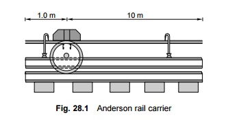
2.The rails are carried using rail tongs and laid on the cess
of the bank almost near the final position. Carrying rails is a strenuous job,
as about 12 to 15 gangmen are required to carry each rail (each rail weighs
about 0.6 t or so). A special type of rail carrier known as the Anderson rail
carrier, shown in Fig. 28.1, can be used for carrying rails with lesser strain.
3. Next the
sleepers are distributed over the length of the formation. The rails have
markings to indicate the final position of the sleepers as shown in Fig. 28.1.
4. Small
fittings such as fish plates and bolts are kept near the joints. The fittings
required for each sleeper are kept near the ends of the sleepers.
5. The rails
are then placed on the sleepers and fixed with the help of fittings, which are
chosen depending upon the type of sleeper. For example, rail screws are used
for fixing rails to wooden sleepers. In the case of steel sleepers, rails are
fixed with the help of keys. Bearing plates are also provided wherever
required, as per the prescribed track standards.
6. The rails
are joined with each other after ensuring that there is sufficient gap between
them. Normally, the initial laying of the tracks is done using three rail
panels. Adequate expansion gaps should be provided in the case of single-rail
as well as three-rail panels. The recommended expansion gaps are provided with
the help of steel liners or shims of appropriate thickness (1 mm to 4 mm),
which are fixed between the two rail ends.
Packing of track The track
is then thoroughly packed with the help of beaters by the
Packing-in-gangs. The following aspects should be examined during this process.
(a) The track
should have a proper gradient.
(b) If the
track is on a curve, it should have proper curvature.
(c) The cross
levels should be even. If a track is to be provided with the recommended
superelevation, this can be achieved by raising the outer rail.
(d) The track
should be thoroughly packed and should be free of hollow spaces.
Ballasting of track The
railway line is normally covered with the ballast after the embankment
has settled and has endured at least two monsoons. Ballasting is generally done
with the help of a ballast train, which has special hoppers that are used for
automatically unloading the ballast onto the track. Alternatively, the ballast is
taken to the cess and then placed on the track manually. Either method ensures
that the ballast is thoroughly packed and inserted properly under the track.
Related Topics