Chapter: Transmission and Distribution : Insulators and Cables
Classification of Cables
CLASSIFICATION OF CABLES
Cables for underground service may be classified in two ways according to
(i) the type of insulating material used in their manufacture
(ii) the voltage for
which they are manufactured. However, the latter method of classification is generally preferred, according to which cables can be divided into the following groups:
Low-tension (L.T.) cables — upto 1000 V
High-tension (H.T.) cables — upto 11,000 V
Super-tension (S.T.) cables — from 22 kV to 33 kV
Extra high-tension (E.H.T.) cables — from 33 kV to 66 kV
Extra super voltage cables — beyond 132 kV
A cable may have one or more than one core depending upon the type of service for which it is intended. It may be
(i) single-core
(ii) (ii) two-core
(iii) (iii) three-core
(iv) (iv) four-core etc.
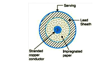
For a 3-phase service, either 3-single-core cables or three-core cable can be used depending upon the operating voltage and load demand. Fig. shows the constructional details of a single-core low tension cable. The cable has ordinary construction because the stresses developed in the cable for low voltages (up to 6600 V) are generally small. It consists of one circular core of tinned stranded copper (or aluminium) insulated by layers of impregnated paper. The insulation is surrounded by a lead sheath which prevents the entry of moisture into the inner parts. In order to protect the lead sheath from corrosion, an overall serving of compounded fibrous material (jute etc.) is provided. Single-core cables are not usually armoured in order to avoid excessive sheath losses. The principal advantages of single-core cables are simple construction and availability of larger copper section.
Cable For 3-Phase
In practice, underground cables are generally required to deliver 3-phase power. For the purpose, either three-core cable or three single core cables may be used. For voltages upto 66 kV, 3-core cable (i.e., multi-core construction) is preferred due to economic reasons. However, for voltages beyond 66 kV, 3-core-cables become too large and unwieldy and, therefore, single-core cables areused. The following types of cables are generally used for 3-phase service :
1. Belted cables — upto 11 kV
2. Screened cables — from 22 kV to 66 kV
3. Pressure cables — beyond 66 kV.
1. Belted Cables
These cables are used for voltages upto 11kV but in extraordinary cases, their use may be extended upto 22kV. Fig.3 shows the constructional details of a 3-core belted cable. The cores are insulated from each other by layers of impregnated paper.
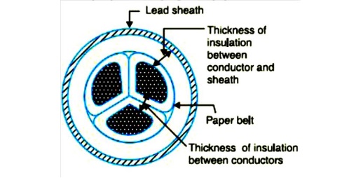
Another layer of impregnated paper tape, called paper belt is wound round the grouped insulated cores. The gap between the insulated cores is filled with fibrous insulating material (jute etc.) so as to give circular cross-section to the cable. The cores are generally stranded and may be of non circular shape to make better use of available space. The belt is covered with lead sheath to protect the cable against ingress of moisture and mechanical injury. The lead sheath is covered with one or more layers of armouring with an outer serving (not shown in the figure).The belted type construction is suitable only for low and medium voltages as the electro static stresses developed in the cables for these voltages are more or less radial i.e., across the insulation. However, for high voltages (beyond 22 kV), the tangential stresses also become important. These stresses act along the layers of paper insulation. As the insulation resistance of paper is quite small along the layers, therefore, tangential stresses set up leakage current along the layers of paper insulation. The leakage current causes local heating, resulting in the risk of breakdown of insulation at any moment. In order to overcome this difficulty, screened cables are used where leakage currents are conducted to earth through metallic screens.
2.Screened Cables
These cables are meant for use up to 33 kV, but in particular cases their use may be extended to operating voltages up to 66 kV. Two principal types of screened cables are H-type cables and S.L. type cables.
(i)H-type Cables
This type of cable was first designed by H. Hochstetler and hence the name. Fig. shows the constructional details of a typical 3-core, H-type cable. Each core is insulated by layers of impregnated paper. The insulation on each core is covered with a metallic screen which usually consists of a perforated aluminum foil. The cores are laid in such a way that metallic screens
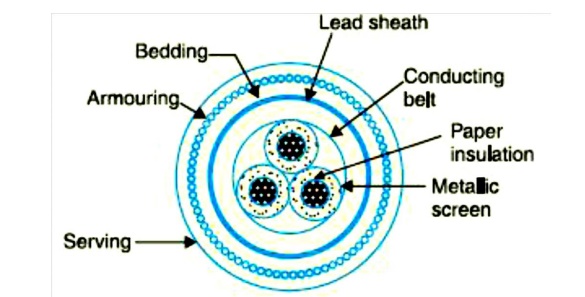
Make contact with one another. An additional conducting belt (copper woven fabric tape) is Wrapped round the three cores. The cable has no insulating belt but lead sheath, bedding, armouring and serving follow as usual. It is easy to see that each core screen is in electrical contact with the conducting belt and the lead sheath. As all the four screens (3 core screens and one conducting belt) and the lead sheath are at earth potential, therefore, the electrical stresses are purely radial and consequently dielectric losses are reduced. Two principal advantages are claimed for H-type cables. Firstly, the perforations in the metallic screens assist in the complete impregnation of the cable with the compound and thus the possibility of air pockets or voids (vacuous spaces) in the dielectric is eliminated. The voids if present tend to reduce the breakdown strength of the cable and may cause considerable damage to the paper insulation. Secondly, the metallic screens increase the heat dissipating power of the cable.
(Ii) s.l. Type cables
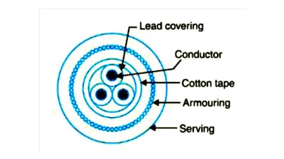
Fig. shows the constructional details of a 3-core S.L. (separate lead) type cable. It is basically H-type cable but the screen round each core insulation is covered by its own lead sheath. There is no overall lead sheath but only armouring and serving are provided. The S.L. type cables have two main advantages over H-type cables. Firstly, the separate sheaths minimize the possibility of core-to-core breakdown. Secondly, bending of cables becomes easy due to the elimination of overall lead sheath. However, the disadvantage is that the three lead sheaths of S.L. cable are much thinner than the single sheath of H-cable and, therefore, call for greater care in manufacture
3. Pressure cables
For voltages beyond 66 kV, solid type cables are unreliable because there is a danger of breakdown of insulation due to the presence of voids. When the operating voltages are greater than 66 kV, pressure cables are used. In such cables, voids are eliminated by increasing the pressure of compound and for this reason they are called pressure cables. Two types of pressure cables viz oil-filled cables and gas pressure cables are commonly used.
(i)Oil-filled cables.
In such types of cables, channels or ducts are provided in the cable for oil circulation. The oil under pressure (it is the same oil used for impregnation) is kept constantly supplied to the channel by means of external reservoirs placed at suitable distances (say 500 m) along the route of the cable. Oil under pressure compresses the layers of paper insulation and is forced in to any voids that may have formed between the layers. Due to the elimination of voids, oil-filled cables can be used for higher voltages, the range being from 66 kV up to 230 kV. Oilfilled cables are of three types viz., single-core conductor channel, single-core sheath channel and three-core filler-space channels.
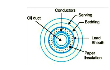
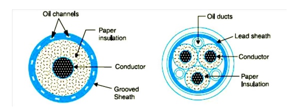
Fig. shows the constructional details of a single-core conductor channel, oil filled cable. The oil channel is formed at the center by stranding the conductor wire around a hollow cylindrical steel spiral tape. The oil under pressure is supplied to the channel by means of external reservoir. As the channel is made of spiral steel tape, it allows the oil to percolate between copper strands to the wrapped insulation. The oil pressure compresses the layers of paper insulation and prevents the possibility of void formation. The system is so designed that when the oil gets expanded due to increase in cable temperature, the extra oil collects in the reservoir. However, when the cable temperature falls during light load conditions, the oil from the reservoir flows to the channel. The disadvantage of this type of cable is that the channel is at the middle of the cable and is at full voltage w.r.t. earth, so that a very complicated system of joints is necessary. Fig. shows the constructional details of a single core sheath channel oil-filled cable. In this type of cable, the conductor is solid similar to that of solid cable and is paper insulated. However, oil ducts are provided in them etallic sheath as shown. In the 3-core oil-filler cable shown in Fig. the oil ducts are located in the filler spaces. These channels are composed of perforated metalribbon tubing and are at earth potential.
(ii)Gas Pressure Cable
The voltage required to set up ionization inside a void increases as the pressure is increased. Therefore, if ordinary cable is subjected to a sufficiently high pressure, the ionization can be altogether eliminated. At the same time, the increased pressure produces radial compression which tends to close any voids. This is the underlying principle of gas pressure cables.
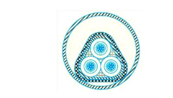
Fig Shows the section of external pressure cable designed by Hochstetler, Vogal and Bowden. The construction of the cable is similar to that of an ordinary solid type except that it is of triangular shape and thickness of lead sheath is 75% that of solid cable. The triangular section reduces the weight and gives low thermal resistance but the main reason for triangular shape is that the lead sheath acts as a pressure membrane. The sheath is protected by a thin metal tape. The cable is laid in a gas-tight steel pipe. The pipe is filled with dry nitrogen gas at 12 to 15 atmospheres. The gas pressure produces radial compression and closes the voids that may have formed between the layers of paper insulation. Such cables can carry more load current and operate at higher voltages than a normal cable. Moreover, maintenance cost is small and the nitrogen gas helps in quenching any flame. However, it has the disadvantage that the overall cost is very high.
Dielectric Stress In Cable
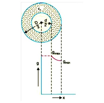
Under operating conditions, the insulation of a cable is subjected to electrostatic forces. This is known as dielectric stress. The dielectric stress at any point in a cable is in fact the potential gradient (or electric intensity) at that point. Consider a single core cable with core diameter d and internal sheath diameter D. As proved in Art 8, the electric intensity at a point x metres from the centre of the cable is
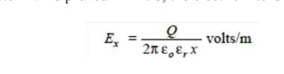
By definition, electric intensity is equal to potential gradient. Therefore, potential gradient g at a point x meters from the Centre of cable is
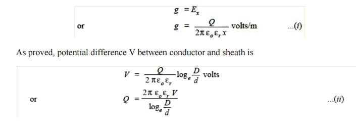
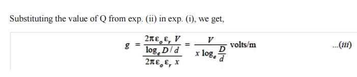
It is clear from exp. (iii) that potential gradient varies inversely as the distance x. Therefore, potential gradient will be maximum when x is minimum i.e., when x = d/2 or at the surface of the conductor. On the other hand, potential gradient will be minimum at x = D/2 or at sheath surface. Maximum potential gradient is
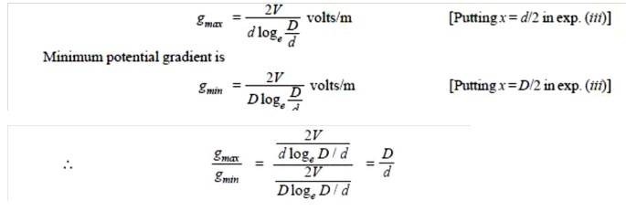
The variation of stress in the dielectric is shown in Fig.14. It is clear that dielectric stress is maximum at the conductor surface and its value goes on decreasing as we move away from the conductor. It may be noted that maximum stress is an important consideration in the design of a cable. For instance, if a cable is to be operated at such a voltage that maximum stress is 5 kV/mm, then the insulation used must have a dielectric strength of at least 5 kV/mm, otherwise breakdown of the cable will become inevitable.
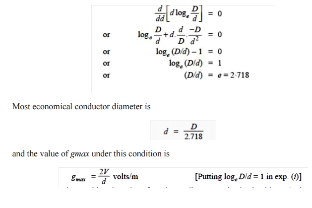
Most Economical Size of Conductor
It has already been shown that maximum stress in a cable occurs at the surface of the conductor. For safe working of the cable, dielectric strength of the insulation should be more than the maximums tress. Rewriting the expression for maximum stress, we get,

The values of working voltage V and internal sheath diameter D have to be kept fixed at certain values due to design considerations. This leaves conductor diameter d to be the only variable in exp.(i). For given values of V and D, the most economical conductor diameter will be one for which gmax has a minimum value. The value of gmax will be minimum when d loge D/d is maximum i.e.
Related Topics