Chapter: Power System Operation and Control : Real Power Frequency Control
Automatic Load Frequency Control
AUTOMATIC LOAD FREQUENCY CONTROL
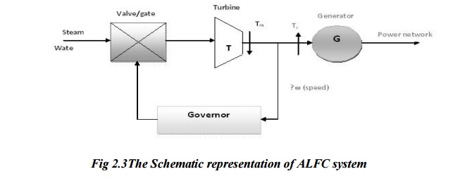
The ALFC is to control the frequency deviation by maintaining the real power balance in the system. The main functions of the ALFC are to i) to maintain the steady frequency; ii) control the tie-line flows; and iii) distribute the load among the participating generating units. The control (input) signals are the tie-line deviation ∆Ptie (measured from the tie- line flows), and the frequency deviation ∆f (obtained by measuring the angle deviation ∆δ). These error signals ∆f and ∆Ptie a r e amplified, mixed and transformed to a real power signal, which then controls the valve position. Depending on the valve position, the turbine (prime mover) changes its output power to establish the real power balance. The complete control schematic is shown in Fig 2.3
For the analysis, the models for each of the blocks in Fig2 are required. The generator and the electrical load constitute the power system. The valve and the hydraulic amplifier represent the speed governing system. Using the swing equation, the generator can be Using the swing equation, the generator can be modeled by
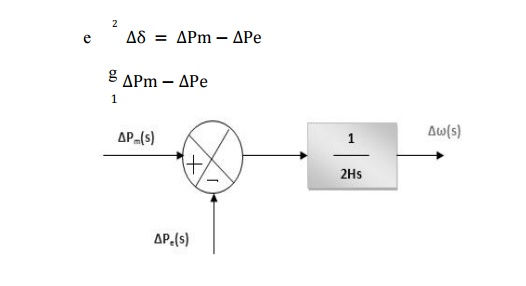
Block Diagram Representation Of The Generator
The load on the system is composite consisting of a frequency independent component and a frequency dependent component. The load can be written as
Pe = P0 + Pf
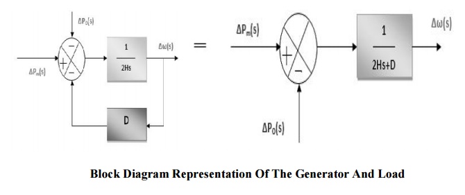
Pe is the change in the load;
P0 - is the frequency independent load component;
Pf - is the frequency dependent load component.
Pf = D
where, D is called frequency characteristic of the load (also called as damping constant) expressed in percent change in load for 1% change in frequency.
If D=1.5%, then a 1% change in frequency causes 1.5% change in load. The combined generator and the load (constituting the power system) can then be represented as shown in Fig. The turbine can be modeled as a first order lag as shown in the Fig.
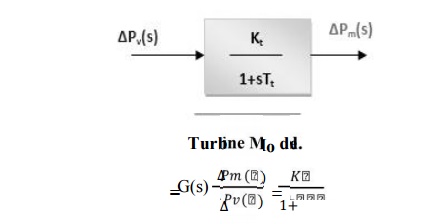
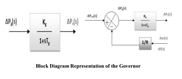
Gt(s) is the TF of the turbine; ∆PV(s) is the change in valve output (due to action). Pm(s) is the change in the turbine output. The governor can similarly modeled as shown Fig. The output of the governor is by
Where ∆Pref is the reference set power, and ∆w/R is the power given by governor speed characteristic. The hydraulic amplifier transforms this signal Pg into valve/gate position corresponding to a power PV.
Thus
PV(s) = (Kg/ (1+sTg)) _Pg(s).
Related Topics