Chapter: Civil : Design Of Reinforced Concrete And Brick Masonry Structures- Yield Line Theory
Yield Line Theory
YIELD
LINE THEORY
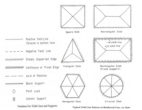
Yield lines -Typical crack
patterns -generated when ultimate moment is reached Characteristics of yield
lines are,
i) Yield
lines are straight
ii) Yield
lines end at supporting edges of slab
iii) Yield
lines passes through intersection of axis of rotation of adjacent slab elements
Axis
of rotation lies along lines of supports and passes over columns

Assumptions:
The
following are the assumptions of the yield line analysis of reinforced concrete
slabs.
1. The
steel reinforcement is fully yielded along the yield lines at collapse.
Rotation following yield is at constant moment.
2.The
slab deforms plastically at collapse and is separated into segments by the
yield lines. The individual segments of the slab behave elastically.
3. The
elastic deformations are neglected and plastic deformations are only
considered. The entire deformations, therefore, take place only along the yield
lines. The individual segments of the slab remain plane even in the collapse
condition.
4. The
bending and twisting moments are uniformly distributed along the yield lines.
The maximum values of the moments depend on the capacities of the section based
on the amount of reinforcement provided in the section.
5. The
yield lines are straight lines as they are the lines of intersection between
two planes.
Rules
of yield lines:
The two terms, positive and negative yield lines, are
used in the analysis to designate the yield lines for positive bending moments
having tension at the bottom and negative bending moments having tension at the
top of the slab, respectively.
The
following are the guidelines for predicting the yield lines and axes of rotation:
1. Yield
lines between two intersecting planes are straight lines.
2. Positive
yield line will be at the mid-span of one-way simply supported slabs.
3. Negative
yield lines will occur at the supports in addition to the positive yield lines
at the mid-span of one-way continuous slabs.
4. Yield
lines will occur under point loads and they will be radiating outward from the
point of application of the point loads.
5. Yield
line between two slab segments should pass through the point of intersection of
the axes of rotation of the adjacent slab segments.
6. Yield
lines should end at the boundary of the slab or at another yield line.
7. Yield
lines represent the axes of rotation.
8. Supported
edges of the slab will also act as axes of rotation. However, the fixed supports
provide constant resistance to rotation having negative yield lines at the
supported edges. On the other hand, axes of rotation at the simply supported
edges will not provide any resistance to rotation of the segment.
Axis
of rotation will pass over any column support, if provided, whose orientation
will depend on other considerations.
Upper
and Lower Bound Theorems
According to the general theory of structural
plasticity, the collapse load of a structure lies in between the upper bound
and lower bound of the true collapse load. Therefore, the solution employing
the theory of plasticity should ensure that lower and upper bounds converge to
the unique and correct values of the collapse load.
The
statements of the two theorems applied to slabs are given below:
(A) Lower
bound theorem: The lower bound of the true collapse load is
that external load for which a distribution of moments can be found
satisfying the requirements of equilibrium and boundary conditions so that the
moments at any location do not exceed the yield moment.
(B) Upper
bound theorem: The upper bound of the true collapse load is
that external load for which the internal work done by the slab for a
small increment of displacement, assuming that moment at every plastic hinge is
equal to the yield moment and satisfying the boundary conditions, is equal to
the external work done by that external load for the same amount of small
increment of displacement.
Thus, the collapse load satisfying the lower bound
theorem is always lower than or equal to the true collapse load. On the other
hand, the collapse load satisfying the upper bound theorem is always higher
than or equal to the true collapse load.
The
yield line analysis is an upper bound method in which the predicted failure
load of a slab for given moment of resistance (capacity) may be higher than the
true value. Thus, the solution of the upper bound method (yield line analysis)
may result into unsafe design if the lowest mechanism could not be chosen.
However, it has been observed that the prediction of the most probable true mechanism
in slab is not difficult. Thus, the solution is safe and adequate in most of
the cases. However, it is always desirable to employ a lower bound method,
which is totally safe from the design point of view.
1. Virtual
work method
2. Equilibrium
method (Equilibrium of individual elements of slab along yield line)
Virtual work method
-Applied load causing virtual displacement is equal to internal work done or
energy dissipated in rotation along the yield lines.
I) Isotropically reinforced -square slab -simply supported -udl
II) Isotropically reinforced -square slab -fixed on all edges -udl
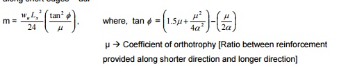
III) Orthotropically reinforced (Diff. rein. bothways) -rectangular slab -simply supported -udl
IV) Orthotropically reinforced -rectangular slab -fixed along long edges - simply supported along short edges -udl
V) Orthotropically reinforced -rectangular slab -all four edges fixed -udl
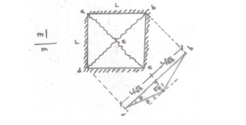
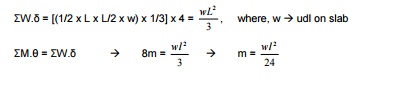
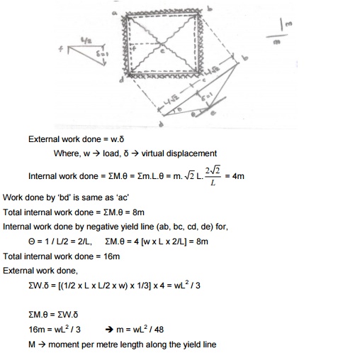
I) Isotropically reinforced -square slab -simply supported -udl
External work done = w.?
![]() Where, w � load,�virtual?
displacement
Where, w � load,�virtual?
displacement
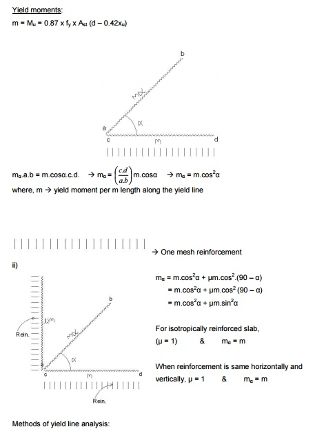
Internal work done = M.? = ?m.L.?
m � Ultimate moment /
unit length
L � Length of yield line
M
� Total moment produced along
all the yield lines
[Opposite
of isotropically reinforced is orthotropically reinforced]
Centre
point is the place where the first ultimate moment is reached and the crack
originates at this point as,
Work done by �bd? is same as �ac? Total internal work
done = ?M.? = 8m
For
a virtual displacement of 1 at centre (i.e) CG of each triangular deflects 1/3
II)
Isotropically reinforced -square slab -fixed on all edges -udl
III)
Orthotropically reinforced (Diff. rein. bothways) -rectangular slab -simply
supported -udl
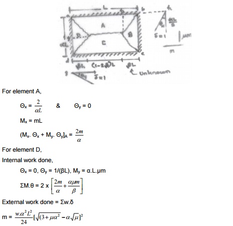
IV)
Orthotropically reinforced -rectangular slab -fixed along long edges - simply
supported along short edges -udl
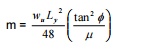
V)
Orthotropically reinforced -rectangular slab -all four edges fixed -udl
1.Design a square slab fixed along all four edges, which
is of side 5m. The slab has to support a service load of 4kN/m2. Use
M20 concrete and Fe415 steel.
As
per IS 456-2000,
l/d
= (0.8 x 35) = 28 �
5000 / 28 = d
d
= 178.6mm = 180mm
Provide D = 200mm
Loading
on slab:
Self
weight = 0.2 x 25 = 5 kN/m2
Live
load = 4 kN/m2
Floor
finish = 1 kN/m2
Total
= 10 kN/m2
Factored
load (wu) = 1.5 x 10 = 15 kN/m2
By
yield line theory, m = wL2 / 48 = =7.8125kNm
Limiting
moment, Mulim = 0.138.fck.b.d2 = 0.138 x 20 x
1000 x 1802 = 89.424 x 10⁶ Nmm Mu < Mulim
K
= Mu/bd2 = 0.241
Ast
= 122mm2
Provide
8mm @ 300mm c/c
1b)
In the above problem, design the slab using IS456 coefficient method.
ly
/ lx = 1
Four edges are discontinuous ?x = y
?=0.056
Mx = x.?w.lx2
= 0.056 x 15 x 52 = 21 kNm My = y.?w.lx2
= 0.056 x 15 x 52 = 21 kNm
�
Required spacing of 8mm bar is 140mm. Provide 8mm @ 140mm c/c.
2. Design a square slab of size 5m, simply supported
along its four edges and subjected to a live load of 4kN/m2.
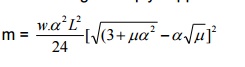
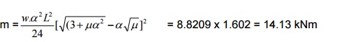
m
=wL2/24
As
per IS 456-2000,
l/d
= (0.8 x 35) = 28 �
5000 / 28 = d
d =
178.6mm = 180mm
Provide
D = 200mm
Loading
on slab:
Self
weight = 0.2 x 25 = 5 kN/m2
Live
load = 4
kN/m2
Floor
finish =
1 kN/m2
Total =
10 kN/m2
Factored
load (wu) = 1.5 x 10 = 15 kN/m2
By
yield line theory, m = wL2/24 = 15.625kNm
Limiting moment, Mulim = 0.138.fck.b.d2
= 0.138 x 20 x 1000 x 1802 = 89.424 x 10⁶ Nmm Mu <
Mulim
Ast
= 247.59mm2
Provide
8mm @ 200mm c/c
3. Design a rectangular slab of size 4m x 6m simply
supported along all its edges, subjected to a live load of 4kN/m2.
The coefficient of orthotrophy is 0.7. Use M20 and Fe415.
For
four edges simply supported condition,
Assume
span/depth = 28 �
Eff.depth = 4000/28 = 142.86mm
Provide
d = 150mm, D = 170mm
Loading
on slab:
Self
weight = 0.17 x 25 = 4.25 kN/m2
Live
load = 4 kN/m2
Floor
finish = = 0.75 kN/m2
Total
= 9 kN/m2
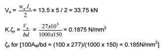
Factored
load (wu) = 1.5 x 9 = 13.5 kN/m2
Limiting
moment, Mulim = 0.138.fck.b.d2 = 62.1 kNm
Mu
< Mulim. The section is under-reinforced.
K =
Mu/b.d2 � Ast
= 277mm2
Minimum
Ast = 0.12% of c/s = 204mm2
Ast
along longerst = span0.7x237
==194mm? 2x< 204A mm2
Provide
8mm @ 240mm c/c
Check
for shear (factored):
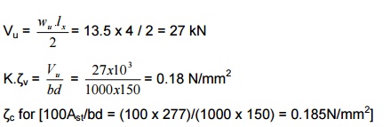
?c
for [100Ast/bd = (100 x 277)/(1000 x 150) =
0.185N/mm2]
0.15 � 0.28
0.25
� 0.36
0.185
� 0.308
As
per Cl.42.4 of IS456-2000,
K
� 1.3 for d = 150mm
K
� 1 for d = 300mm
K
� ((1.126 + 0.133) = 1.26) for d = 170mm
K.
?c= 1.26 x 0.308 = 0.388 N/mm2 > v (0?.18
N/mm2)
Section
is safe in shear.
4.In
the above problem, design the slab if all the supports are fixed. For four
edges simply supported condition,
K. ?c=
1.26 x 0.308 = 0.388 N/mm2 > v (0?.18 N/mm2)
Section
is safe in shear.

5.
Solve the above problem if two long edges are fixed.
Provide
8mm @ 240mm bothways.
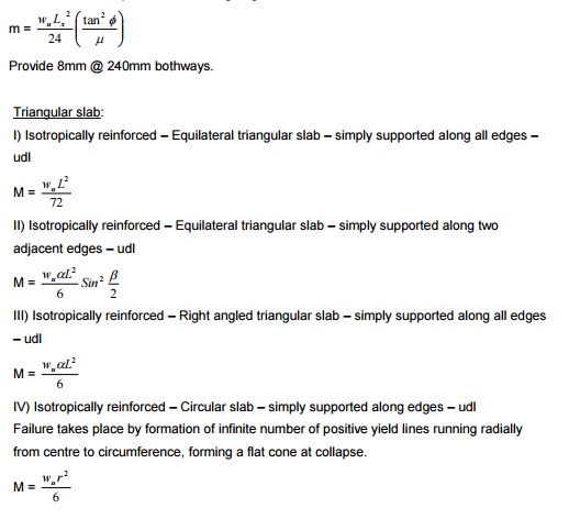
Triangular
slab:
I)
Isotropically reinforced -Equilateral
triangular slab -simply supported along all edges - udl
II)
Isotropically reinforced -Equilateral
triangular slab -simply supported along two adjacent edges -udl
III)
III) Isotropically reinforced -Right angled
triangular slab -simply supported along all edges -udl
IV)
Isotropically reinforced -Circular slab -simply supported along edges -udl ailure takes place by formation of infinite
number of positive yield lines running radially om centre to circumference, forming a flat
cone at collapse.
6. Design an equilateral triangular slab of side 5m,
isotropically reinforced and is simply supported along its edges. The slab is
subjected to a superimposed load of 3kN/m2. Use M20 concrete and Fe415 steel.
Assume
span/depth = 28 �
Eff.depth = 5000/28 =
178.57mm
Provide d = 180mm, D = 200mm
Loading
on slab:
Self
weight = 0.2 x 25 = 5 kN/m2
Live
load = 3 kN/m2
Floor
finish = 1 kN/m2
Total
= = 9 kN/m2
Factored
load (wu) = 1.5 x 9 = 13.5 kN/m2
Limiting
moment, Mulim = 0.138.fck.b.d2 = 89.42 kNm Mu
< Mulim. The section is under-reinforced.
K =
Mu/b.d2 � Ast
= 72.754mm2
Minimum
Ast = 0.12% of c/s = 240mm2
Ast
< min Ast [240 mm2]
Provide
8mm @ 200mm c/c
Check
for shear (factored):
0.185N/mm2]
0.13 � 0.28
As
per Cl.42.4 of IS456-2000,
K � 1.3 for d =
150mm
K � 1 for d =
300mm
K � ((1.04 + 0.2) = 1.24) for d = 180mm
K. ?c=
1.24 x 0.28 = 0.3472 N/mm2 > v (0?.18 N/mm2)
Section
is safe in shear.
Related Topics