Chapter: Civil : Design Of Reinforced Concrete And Brick Masonry Structures- Retaining Walls: Design Of Water Tank
Design Of Water Tank

DESIGN OF WATER TANK
Classication:
1.
C Cylindrical
2.
Rectangular
Further,
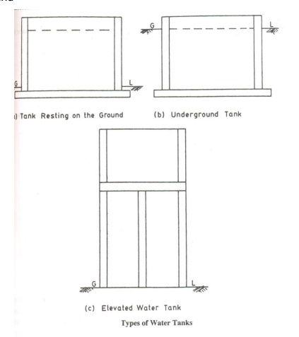
water tanks are classified based on their positions as,
1. Resting
on ground
a. Flexible
or free base
b. Hinged
c. Fixed
2.
Elevated or overhead
3.
Underground
Components
of water tank:
1. Side
Walls [Rectangular or cylindrical]
2. Base
slab
3. Cover
slab or dome
4. Staging
[Overhead] ŕ
Columns, Beams, Bracings
Types
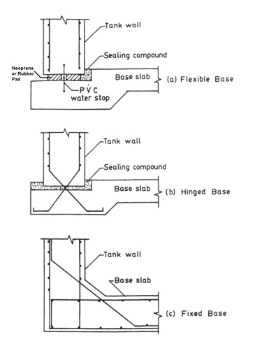
of Joints:
i)
Flexible base
ii)
Hinged base
iii)
Fixed base
Water pressure distribution:
1. On side
walls, it acts
linearly varying fr
2. On base
slab, uniform pressure
acts with i
Permissible stresses:
The method of design adopted
for design of water tank is working stress method. The permissible stress
values in concrete and steel are given in Tables 21 and 22 of IS456-2000, as
follows:
For M20 ŕ ?cbc
= 7 N/mm2, t =?5 N/mm2
2
For Fe250 steel,-140N/mm?st = 130
2
For Fe415
steel,-240N/mm?st = 230
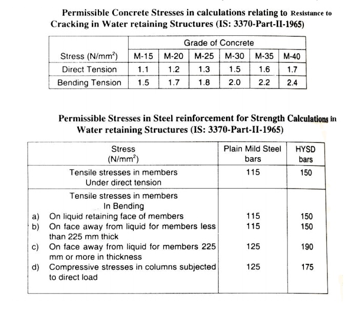
For
liquid retaining structures, the stress values are further reduced and given in
IS3370
Part
II [Reinforced concrete structures].
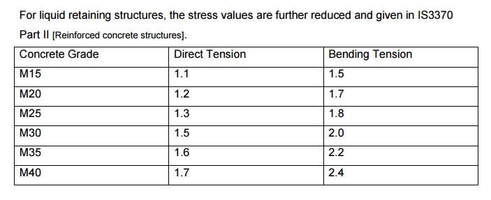
Concrete Grade, Direct Tension , Bending Tension
M15 1.1 1.5
M20 1.2 1.7
M25 1.3 1.8
M30 1.5 2.0
M35 1.6 2.2
M40 1.7 2.4
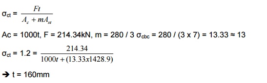
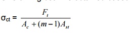
As per clause B -2.1.1, the
tensile stress is given by,
?= Ft / Ac
+ +mAst
where, m ŕ modular
ratiocbc= Es=/E c 280
/ 3 ?
?cbc is the
permissible compressive stress.
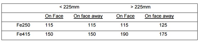
Permissible stress in steel is given in IS3370 Part II as, Tensile stress: Fe250 ŕ 115 N/mm2, Fe415 ŕ 150 N/mm2
Bending stress:
Reinforcement
requirements: [As per IS3370]
1. Minimum
Ast is 0.3% for 100mm section and 0.2% for 450mm section.
2. If
thickness exceeds 200mm, the reinforcement is provided in double layers. A
minimum cover of 25mm is provided along the liquid retained face and the cover
is increased by 12mm (37mm) if the wall is subjected to aggressive soil or
liquid.
HOOP TENSION AND BENDING
MOMENTS IN CYLINDRICAL TANK WALLS
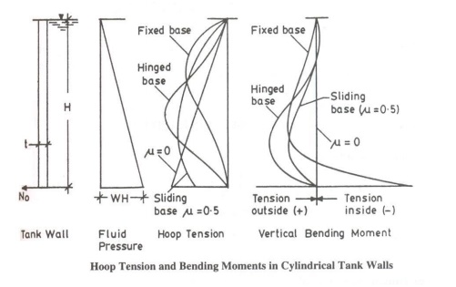
CYLINDRICAL TANK WITH FLEXIBLE BASE:
The wall is designed for
hoop stress, for which circumferential horizontal steel is provided. Minimum
reinforcement is provided along the vertical direction
1) Design
a circular water tank with flexible base for a capacity of 4 lakh litres with
the tank having a depth of 4m, including a free base of 200mm. Use M20 concrete
and Fe415 steel. Area of water tank = Volume / Height
= 400 / 4 = 100m2
Provide a diameter of 11.5m
The height of water to be retained = 3.8m
The wall is subjected to hoop tension acting along the
circumferential direction. The hoop tension per metre height is given by,
Hoop
tension = g.h.D / 2 = (9.81 x 3.8 x 11.5)/2 = 214.34 kN
Permissible stress in tension as per IS3370 for Fe415
steel is 150 N/mm2.
Ast required = 214.34 x 10³ / 150 =
1428.9 mm2
Spacing = 1000.ast / Ast, ŕ 16mm @ 140mm c/c
Thickness of tank is adopted based on the tensile stress
concrete can take.
Minimum thickness as per
empirical formula is, tmin = (30h + 50)mm where h ŕ m
= 30 x 3.8 + 50 = 164mm
Provide a thickness of 170mm.
Minimum reinforcement is provided as vertical steel.
Minimum Ast is 0.3% for 100mm section and 0.2% for 450mm section.
Therefore, for 170mm thickness, Ast
required is 0.28% of c/s
Ast = (0.28/100) x 1000 x 170 = 476mm2
Provide 8mm @ 100mm c/c
Curtailment of reinforcement:
At 2m height,
Hoop tension = g.h.D / 2 = (9.81 x 1.8 x 11.5) / 2 = 101.5335 kN
Ast = 101.535 x 10³ / 150 = 676.89 mm2
Provide 10mm @ 110mm c/c (or) 16mm @ 290mm c/c
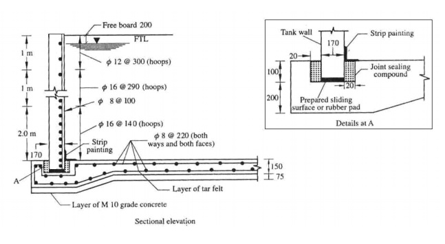
Design of base slab:
Since the base slab rests
directly on the ground, a nominal thickness of 150mm is provided and a minimum
reinforcement of 0.3% of c/s is provided along both ways and along both the
faces.
0.3% of c/s ŕ 0.3/100 x 150 x 1000 = 450 mm2,
Required 8mm @110 mm c/c Provide 8mm @220 mm c/c on both faces.
Below the base slab, a layer of lean concrete mix M20 is
provided for 75mm thickness with a layer of tar felt.
Design of dome: -
Roof covering for cylindrical water tanks
[A dome acts as a roof covering for cylindrical water
tanks. The dome slab is cast between the ring beams provided at the top edge of
the side walls of the water tank. The dome is designed for meridonial thrust
and hoop force].
2) In the above problem,
design a spherical dome having a central rise of one fifth the diameter.
Height = 1/5 x 11.5 = 2.3m
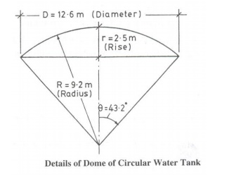
Radius of curvature of the
dome [R] R2 = (R -2.3)2 + 5.752
ŕ R =
8.33m
Cos? =
6.04 / 8.33
= 0.724
The dome is subjected to
meridonial thrust and hoop force, for which the permissible stress should be
within permissible compressive strength of concrete.
?c = 5 N/mm2
Assume thickness of dome as 100mm
Meridonial thrust, T = WR / 1+ +Cosq
w? is the
loading of
and any live load acting on it.
Self weight of slab
= 0.1 x 25 = 2.5 kN/m2 = 2kN/m2
W = 4.5 kN/m2
T = 4.5x8.3 / 1 +0.74 = =
21.46kN
Meridonial thrust = T / (c/s area) = 21.46 x 10³
/ (100 x 1000) = 0.21 N/mm2 < 5 N/mm2 The hoop stress
developed in dome slab is given by,
The provided 100mm section
is sufficient. Minimum reinforcement of 0.3% of c/s is provided both ways.
0.3% of c/s = 0.3/100 x 1000 x 100 = 300mm2 ŕ 8mm
@ 160mm c/c
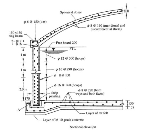
Design of ring beam:
The horizontal component of
meridonial thrust acts on the ring beam. The horizontal thrust, Ast
= HL Comp / s ? where, HL Comp = T.Cos? x D/2 3
x=0 .7421x5.7546=91 .3kNx 10 Ast = 91.3 x 10³ / 150 = 608 mm2
Provide (2#
16mm?ŕ(626mm+2#) 12mm?)
Size of ring beam is obtained based on tensile stress
relation,
Here ring beam is not
subjected to water load. So, permissible tensile stress for M20 concrete is 2.8
N/mm2 (Annex B-3.11) of IS456-2000.
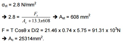
?ct = 2.8 N/mm2
F = T Cos?
x D/2 =
21.46N x 0.74
x 5.75 =
91.3
č Ac
= 25314mm2.
Provide 150 x 150 mm size of ring beam with (2# 16mm? +
2# stress is developed, the steel will take the tensile stress.
DESIGN OF CYLINDRICAL WATER TANK: [With fixed base]
For cylindrical tanks fixed at the base, bending moment
and hoop tension are developed,
whose values are based on non-dimensional parameter, H 2 /
Dt .
The vertical reinforcement is provided for the bending moment developed
and the transverse reinforcement is provided for hoop tension developed.
The coefficients of the non-dimensional parameter H 2/Dt are given in Tables 9 (HT) and 10 (BM).
Maximum hoop tension =
Coefficient x W.H.D/2 Bending moment = Coefficient x w.H3
Where, R ŕ
Radius of tank, D ŕ
Diameter of tank
3)In the above problem, design a water tank for fixed
base condition. Permissible stresses
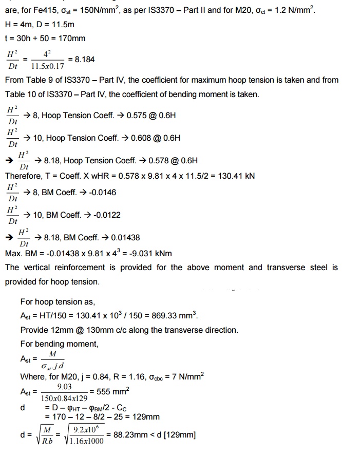
Min. depth required = 88.23mm
0.3% of c/s (vertical steel)
= 0.28/100 x 1000 x 170 = 476 mm2 Provide 8mm @ 100mm c/c
The maximum of Ast for BM at
Ast {maximum} is provided as vertical reinforcement
[555mm2]. Provide 8mm @ 90mm c/c
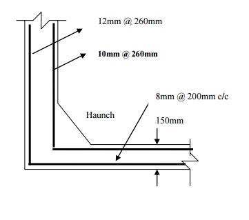
Provide 10mm @ 130mm c/c as
vertical reinforcement. If the reinforcement is provided as double layers on
both the faces, the spacing is doubled.
Provide 10mm @ 260mm c/c as
vertical reinforcement along the two faces with transverse hook reinforcement
at 12mm @ 260mm c/c along both the faces.
Design of base slab:
Provide a nominal thickness
of 150mm for base slab with 0.3% distribution steel [8mm @ 200mm c/c, along
both faces, both ways].
Also
provide a haunch of size 160mm at the junction of the wall and the base slab.
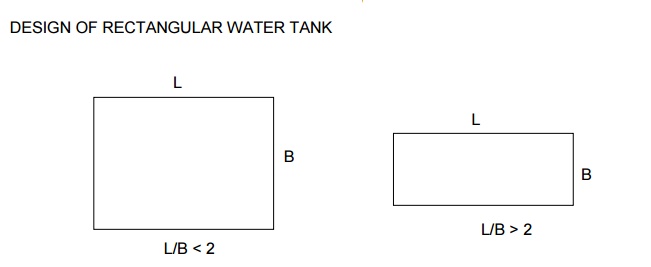
When L / B < 2,
cantilever moment generates at the base and maximum bending action takes place
along the continuous edges of the side walls in both short and long direction.
When L / B > 2, only cantilever action takes place in long wall. Whereas, a
short wall is designed for horizontal bending and cantilever action.
[Cylindrical ŕ
Hoop Tension ŕ
Transverse reinforcement ]
When L/B < 2,
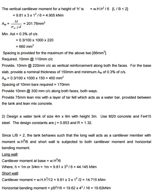
i) Cantilever moment at base = w.H.h2 / 6
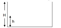
where, h = 1m or H/4, whichever greater
ii) For horizontal bending of the walls, the maximum
moment is found from,
a)
Fixed end moments,
PL2/12 and PB2/12
b)
Positive moment at midspan,
Mf
= PL2/8 & Mf = PB2/8
Where, Mf is the
final moment at the supports (junction between long wall and short wall). The
maximum value is taken for design. Here,
P ŕ water pressure given as p = w(H -h)
For the maximum moment, the area of steel along the
longer direction and shorter direction are found from the relation,
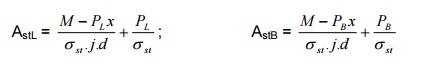
Where, PL & PB are tension in
long and short walls p -Pressure exerted by water
Tension
in the walls is given by, PL = p x B/2 & PB = p
1. Design a rectangular tank
of size 4m x 6m with height 3m. The tank rests on firm ground. Use M20 concrete
and Fe415 steel. Take design constants j = 0.853 & R = 1.32.
Pressure exerted by water, p = w (H -h)
Where, h = 1m or H/4 č 1m or 0.75m = 1m [greater]
P = 9.81 (3 -1) =
19.62 kN/m2
To find the final moment at
the junction of long wall and short wall based on the fixed end moment and
distribution factor, the moment distribution is done.
Joint A:
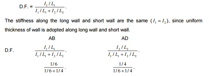
The stiffness along the long wall and short wall are the
same ( I1 =I 2 ),
since uniform thickness of wall is adopted along long wall and short wall.
Short wall is stiffer than the long wall.
MFAB = pL2 / 12 = 19.62 x 62
/ 12 = 58.86 kNm (3p)
MFAD = pB2 / 12 = 19.62 x 42
/ 12 = 26.16 kNm (1.33p)
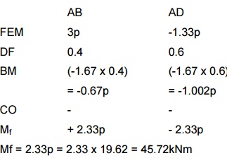
Joint A,
AB AD
FEM 3p -1.33p
DF 0.4 0.6
BM (-1.67 x 0.4) (-1.67 x 0.6) = -0.67p = -1.002p
CO - -
Mf + 2.33p - 2.33p
Mf = 2.33p = 2.33 x 19.62 = 45.72kNm
Moment at midspan,
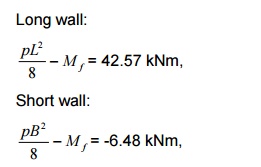
The reinforcement is
provided for maximum moment generated. Therefore, maximum moment generated in
the water tank is 45.72kNm.
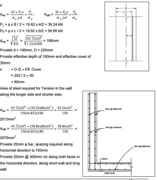
Provide 20mm spacing
? required bar, along horizontal direction is 150mm Provide 20mm @ 300mm c/c
along both faces in the horizontal direction, along short wall and long wall.
Min. Ast = 0.3% of c/s
= 0.3/100
x 1000 x 220
= 660
mm2
Spacing is provided for the
maximum of the above two [66mm2] Required, 10mm @ 110mm c/c
Provide, 10mm @ 220mm c/c as
vertical reinforcement along both the faces. For the base slab, provide a
nominal thickness of 150mm and minimum Ast of 0.3% of c/s.
Ast = 0.3/100 x
1000 x 150 = 450 mm2 Spacing of 10mm bars required = 170mm
Provide 10mm @ 300 mm c/c along both faces, both ways.
Provide 75mm lean mix with a
layer of tar felt which acts as a water bar, provided between the tank and lean
mix concrete.
2) Design a water tank of
size 4m x 9m with height 3m. Use M20 concrete and Fe415 steel. The design
constants are j = 0.853 and R = 1.32.
Since L/B > 2, the tank
behaves such that the long wall acts as a cantilever member with moment w.H3/6
and short wall is subjected to both cantilever moment and horizontal bending
moment.
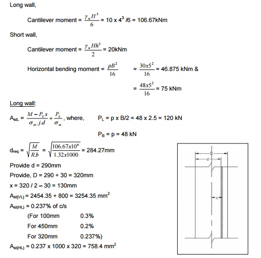
Long wall:
Cantilever moment at base = w.H3/6
Where, h = 1m or 3/4m = 1m =
9.81 x 33 / 6 = 44.145 kNm Short wall:
Cantilever moment = w.H.h2/12 = 9.81 x 3 x 12
/2 = 14.715 kNm
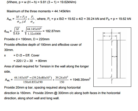
Horizontal bending moment =
pB2/16 = 19.62 x 42 / 16 = 19.62kNm (Where, p = w (H -h)
= 9.81 (3 -1) = 19.62kN/m)
Maximum of the three moments
= 44.145kNm
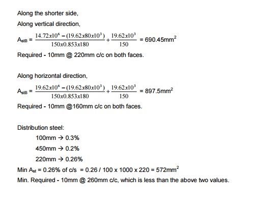
Required - 10mm @160mm c/c on both faces.
Distribution steel:
100mm - > 0.3%
450mm - > 0.2%
220mm - > 0.26%
Min Ast = 0.26% of c/s = 0.26 / 100 x 1000 x 220 = 572mm2
Min. Required - 10mm @ 260mm c/c, which is less than the
above two values.
Base slab:
Since base slab is resting
directly on the ground, nominal thickness of 150mm is provided and minimum
reinforcement of 0.3% of cross-section is provided both ways along both faces.
Ast required =
0.3% of c/s = 465mm2. Provide 8mm @ 200mm c/c.
Below the base slab, a layer
of lean concrete mix is provided with 75mm thick tar felt layer between them.
DESIGN OF UNDERGROUND WATER TANK
Design of underground water
tank is similar to that of tanks resting on grounds (for rectangular water
tanks based on L/B ratio), where additional moment if any due to the earth
pressure on the side walls need to be considered. If the soil is submerged, pressure
exerted by water is also considered. Thus the side walls are checked for the
two critical conditions,
i) No earth pressure with wpressure(H-h) from wa
ii) Earth pressure exerted on wall under tank empty condition, -?pw)+?=H/3w.(?
The tank has to be checked
for uplift water pressure for which frictional resistance should be sufficient.
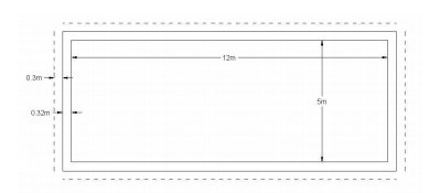
Design an underground water
tank of size 12m x 5m with height 4m. The density of soil is 16kN/m3
and coefficient of friction between soil and concrete is 0.15. The soil is
saturated. Here, L / B = 12 / 5 = 2.4 > 2
The tank walls are checked for two critical conditions,
i) No earth
pressure with wpressure(H-h) from
wa
= 10
(4-1) = 30kN/m2
ii) Earth pressure
exerted on wall
under-?w)+?wH
tank
= 48kN/m2
Where,
h = 1m or (H/4 = 1m)
Therefore, the maximum
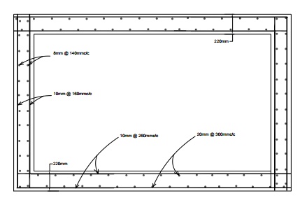
pressure is used in finding out bending moment on the wall. Long wall,
Provide 10mm @ 200mm c/c
Short wall:
Ast(VL) = 370.8 + 320 = 690.8 mm2
< Astmin
Provide Astmin, 10mm @ 200mm c/c
Ast(HL) = 2173.09 mm2
Provide 16mm @ 180mm c/c
Check for uplift:
The tank is checked for
uplift pressure. When the uplift pressure exceeds the downward load due to the
self weight of the tank and the frictional resistance required. The base slab
is projected all around thereby increasing the downward load. The pressure of
submerged earth and water at the bottom of the base slab for 1m length of the
wall is found. The frictional resistance of the tank is found by multiplying
the coefficient of friction between soil and concrete with the pressure
exerted.
Assume the thickness of the
base slab as 400mm and provide a projection of 300mm all around the water tank.
Downward load due to self weight of tank:
Long wall = 2 x 12.64 x 0.32 x 4 x 25 = 808.36 kN
Short wall = 2 x 5 x 0.32 x 4 x 25 = 320 kN
Base slab = (12.64 + 0.6).(5.64 + 0.6) x 0.4 x 25 = 826.176kN
Total = 1955.136 kN
Weight of earth retained over projection,
Long wall = 2 x (12.54 + 0.6) x 4 x 0.3 x 16 = 508.42 kN
Short wall = 2 x 5.64 x 4 x 0.3 x 16 = 216.576 kN
= 724.996
kN
Total
load = 2680.132 kN
Frictional force required = 3635.174 -2680.132 = 955 kN
Pressure exerted by water at a depth of 4.4m,
p = H -/?w)3w.+H(?
= 4.43 (16
-10) + 10 x 4.4 = 52.8 kN/m2
![]()
Considering 1m length of wall, the force exerted is = ˝ x
H x p
= ˝ x 4.4 x 52.8 =
116.16kN/m The frictional resistance per metre length of wall = µ.F = 0.15 x 116.16 = 17.424 kN/m For the
entire perimeter of the wall, the frictional resistance offered,
= 2
x (12.64 + 5.64) x 17.42 = 637 kN < 955 kN
Hence the downward load due
to self weight and cantilever projection of bse slab is insufficient against
the uplift force. The length of projection has to be increased. Increase the
base projection to 0.7m, all around.
Downward load due to self weight of tank:
Long wall = 2 x 12.64 x 0.32 x 4 x 25 = 808.36 kN
Short wall = 2 x 5 x 0.32 x 4 x 25 = 320 kN
Base slab = (12.64 + 1.4).(5.64 + 1.4) x 0.4 x 25 = 988.416kN
Total = 2116.78 kN
Weight of earth retained over projection,
Long wall = 2 x (12.54 + 1.4) x 4 x 0.3 x 16 = 1257.98 kN
Short wall = 2 x 5.64 x 4 x 0.7 x 16 = 505.34 kN
= 1763.32
kN
Total
load = 3880.1 kN
Frictional force required = 4349.03 -3880 = 469.03 kN
< 637 kN
(Frictional force offered by walls)
p = 52.8 kN/m2.
The water tank is safe against uplift.
The base is design as a
continuous slab, supported between two short walls, for the self weight and
weight of side walls.
Design of base slab:
Loading on the base slab
includes the self weight of base slab and weight of side walls. Considering 1m
strip,
Weight of base slab = 7.04 x 0.4 x 25 = 70.4 kN/m
Weight of walls = 2 x 4 x 0.32 x 25 = 64
kN/m
Total = 134.4 kN/m
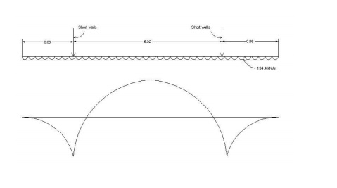
Reaction at the support =
134.4 x 7.04 / 2 = 473.09 kN B.M. at the support = w.l2/2 = 134.4 x
0.862 / 2 = 49.7 kNm
B.M. at centre = 134.4 x
3.522 / 2 -473.09 (2.66) = -425.8kNm [sagging moment]
[D = 400mm, d = 400 -35 = 365mm] Provide 25mmř in two layers [both faces].
Provide 25mm @ 100mm c/c on
both faces.
Related Topics