Chapter: Civil : Design Of Reinforced Concrete And Brick Masonry Structures- Retaining Walls: Design of cantilever and counter fort retaining walls
Design Of Retaining Walls
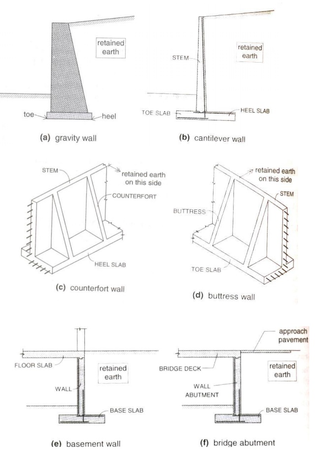
Retaining
wall -Retains Earth -when level difference exists between two surfaces
A) Gravity
wall (h<3m) -Masonry or Stone
B) Cantilever
wall (h>3m and h<6m)
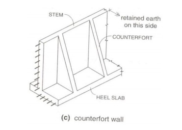
C) Counterfort
wall (h>8m)
D) Buttress wall [Transverse stem support
provided on front side]
E)E) Bridge abutment [Additional horizontal restraint from bridge deck]
A) Gravity wall (h<3m) -Masonry or Stone
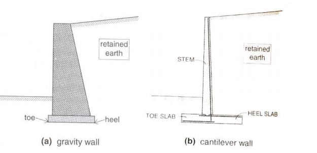
B) Cantilever wall (h>3m and h<6m)
C) Counterfort wall (h>8m)
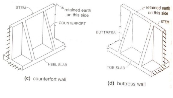
D) Buttress wall [Transverse stem support provided on front side]
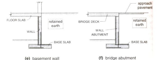
E)E) Bridge abutment [Additional horizontal restraint from bridge deck]
Stability -Overturning and Sliding -Avoided by providing sufficient base width.
Earth
pressure and stability requirements:
Pressure,
P
=CgZ
Where, Z = depth, g = Unit weight
Ca = 1
-Sinf / 1
+Sinf
Cp = 1 +Sinf / 1 -Sinf
Always, Cp > Ca.
Eg: If0, Ca?= 1/3=and30Cp = 3.
In sloped backfill,
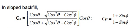
1.Effect of surcharge on
level backfill:
Pa = Pa1 + Pa2,
where,
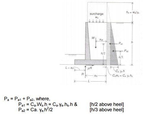
Note : Purpose of retaining wall
is to retain earth and not water. Therefore, submerged condition should be
avoided by providing and maintaining proper drainage facilities [including
provision of weep holes].
2. Effect of water in the
backfill:
Stability requirements

ii)
Sliding: [Friction between base slab and supporting soil]
F = ?.[where,R R = W]
R
-> Resultant soil pressure at footing base
?->
Coefficient of static friction [0.35 -Silt & 0.60 -Rough rock]
FOSsliding
= 0.9F
/ Pa Cosq ?
1.4
When Pa is very high, shear key
projection can be provided below footing base [Produces passive resistance Pps,
which is generally neglected, otherwise].
Sliding is reduced by
providing shear key [like a plug, anchors inside]
Pps =Cge(h2
2 -h12
)
/ 2
Xsk
-> Flexural reinforcement from stem is extended straight into shear key near
the
toe.
Note: For economical design,
soil pressure resultant(R) must be in line with front face of wall.
Preliminary
proportioning of cantilever retaining wall:
1. The
thickness of base slab is h/12 or 8% of the height of wall + surcharge.
2. The
base thickness of stem should be greater than the thickness of base slab
3. The
top thickness of stem should not be less than 150mm.
4. Clear
cover for stem is 50mm and base slab is
75mm
5. Minimum
length of base slab is given by
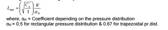
where,R=Coefficient?
depending on the pressure distribution
?R
= 0.5 for rectangular pressure distribution & 0.67 for trapezoidal pr.dist.
6. Minimum
length of heel slab is given by
Notes:
1. The
critical section for moment is at front face of stem.
2. The critical
section for shear
is at �d? f
3. The
stem, heel and toe slabs are designed as cantilever slabs for the resultant
pressure.
4. Temperature
and shrinkage reinforcement is provided as 0.12% of cross section along the
transverse direction to the main reinforcement and front face of the stem.
1. Determine suitable
dimensions of a cantilever retaining wall, which is required to support a bank
of earth 4.0m high above ground level on the toe side of the wall. Consider the
backfill surface to be inclined at an angle of 15o with the
horizontal. Assume good soil for foundation at a depth of 1.25m below ground
level with SBC of 160kN/m2. Further assume the backfill to comprise
of granular soil with unit weight of 16kN/m3 and an angle of
shearing resistance of 30o. Assume the coefficient of friction
between soil and concrete to be 0.5.
Given: h = 4.0 + 1.25m
? =o 15 ? = o 30
re = 16kN/m3
qa = 160kN/m2
? = 0.5
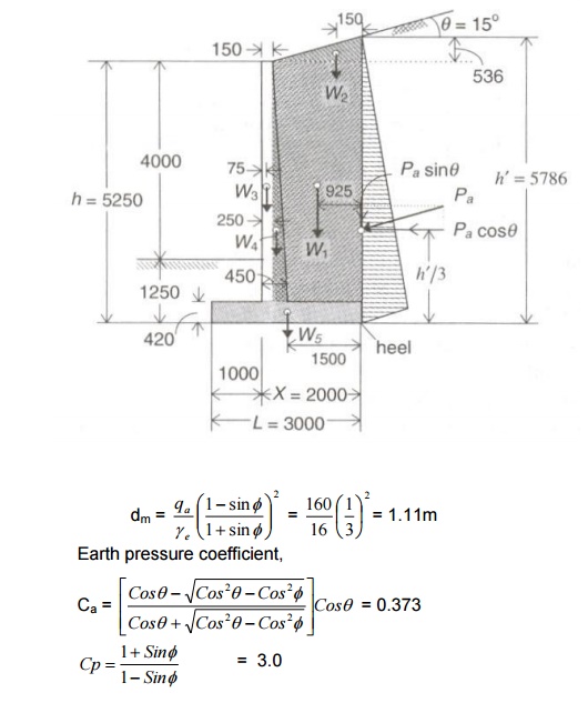
Minimum depth of
foundation (Rankine?s),
Preliminary
proportioning:
Thickness
of footing base slab = 0.08h = 0.08 x 5.25 = 0.42m
Provide
a base thickness of 420mm for base slab.
Assume
stem thickness of 450mm at base of stem tapering to 150mm at top of wall.
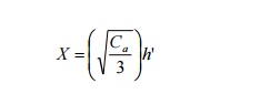
For economical proportioning
of length �L?, a be in line with front face of the stem.
height
above wall]
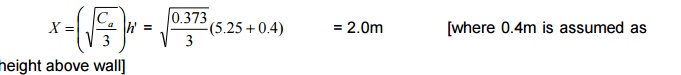
Assuming a triangular base
pressure distribution, L = 1.5X = 3.0m
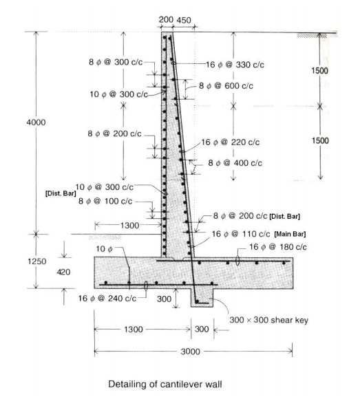
Preliminary
proportions are shown in figure.
For the assumed proportions, the retaining
wall is checked for stability against overturning and sliding.
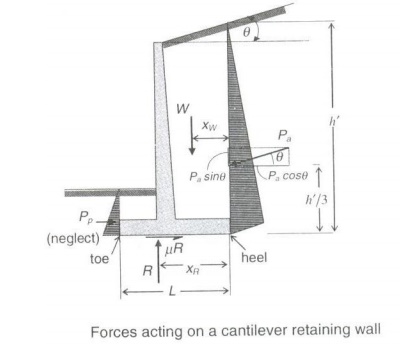
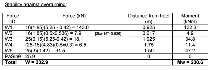
Stability against
overturning:
Pa = Active pressure exerted by retained
earth on wall [both wall and earth move in same direction]
Pp
= Passive pressure exerted by wall on retained earth [both move in opposite
direction]
Ca -> same for dry and
submerged condition, si significantly.
Force due to active pressure,
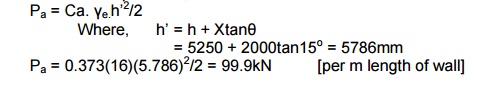
Pa = 0.373(16)(5.786)2/2 = 99.9kN [per
m length of wall]
FOS = 0.9
x Stabilising force
or moment / Destabilising force
or moment
Therefore,
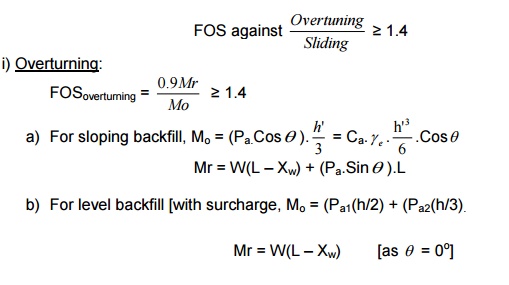
FOS(overturning) = 0.9Mr / Mo ? 1.4
Overturning moment, Mo
= (PaCos?)h?/3 = 96.5(5.786/3) =
186.
To find the distance of
resultant vertical force from heel,
Distance
of resultant vertical force from heel,
Xw
= Mw/W = 230.6/232.9 = 0.99m
Stabilising
moment (about toe),
Mr = W(L -Xw)
+ PaSin?(L) =-0 .99)232+77.69(3 = 468.1kNm [per m length of wall]
FOS(overturning) = 0.9Mr
/ Mo = 0.9x(468.1 +77.6) / 186.1 = 2.26 > 1.40
Soil
pressure at footing base:
Resultant vertical reaction,
R = W = 232.9kN [per m length of wall]
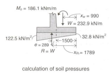
Distance
of R from heel, LR = (Mw + Mo) / R = (230.6 +
186.1)/232.9 = 1.789m
Eccentricity,
e = LR -L/2 = 1.789 -3/2 = 0.289m < L/6 ->[0.5m]
Hence
the resultant lies within the middle third of the base, which is desirable.
Maximum pressure as base,
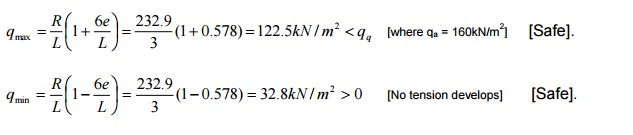
Stability
against sliding:
Sliding force, PaCos? =
96.5kN
Resisting force, F
= ?R =[Ignoring0 .passive5 pressurex232ontoe.side]9 =
116.4
FOS(Sliding) = 0.9F
/ Pa Cosq = 0.9x116.4 / 96.5
= 1.085 <1.40 [Not sufficient]
Hence
a shear key may be provided.
Assume a shear key 300mm x
300mm at a distance of 1300mm from toe as shown in figure.
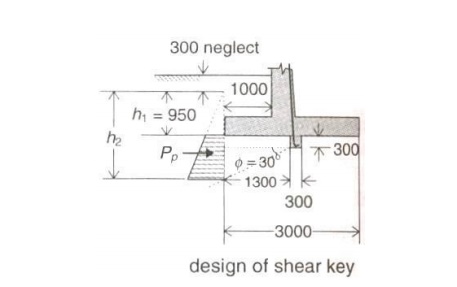
h2 = 950 + 300 + 1300tan30o = 2001mm
Pp = Cp.e?.(h22
-h12)/2 = 3 x 16 x (2.0012 -0.9502)/2
= 74.11kN.
FOS (Sliding) = 0.9(116.4
+74.44) / 96.5 =1.78 >1.4
[SAFE]
Design of toe slab:
Assuming a clear
cover of 75mm
and 16mm ?
use
d
= 420 -75 -8 = 337mm
Vu
= 1.5 [112 +81.9 / 2] x(1 - 0.337) =
96.42kN [Vu is
design shear at
�d? from fac
Mu = 1.5{(81.9 x
12/2) + (112 - 81.9) x 1/2 x 12 x
2/3} = 76.48 kNm/m length
Nominal shear stress, t = V/ bd = 96.42x10³
/ 1000x337 =0.286N
/ mm2
Using M20
concrete,
For a t =0.29N/mm2,
pt (required) = 0.2%
K = M u bd 2 = 76.48x10⁶
/ 1000x3372 =0.673N / mm2
For pt = 0.2%, Ast
= 0.2/100 x 1000 x 337 = 674 mm2 / m
Spacing
= ( 1000xpx162 / 4 )
/ 674 =
298mm
Provide
16mmf @ 290mm c/c at bottom of
toe slab
Ld
= fs s / 4t bd = (16).0.87
f y / 4t
bd = 752mm, beyond face of stem.
Since
length available is 1m, no curtailment is sorted.
Design
of heel slab:
Vu = =128.06kN
Mu
= 1.5{(82.54 x 1.552/2) + (128.6 - 82.54) x 1/2 x 1.552 x
2/3}
= 203.96 kNm/m length
Nominal
shear stress, t = V / bd = 128.06x10³
/ 1000x337 = =0.38N / mm2
Using M20 concrete,
For a t =0.39N/mm2,
pt (required) = 0.3%
K = M u / bd 2 = 203.96x10⁶
/ 1000x3372 = 1.8N
/ mm2
For pt = 0.565%,
Ast = 0.565/100 x 1000 x 337 = 1904.05 mm2 / m
Spacing
= (1000xpx162 / 4) / 1904.05
=
105.61mm
Provide
16mmf @ 100mm c/c at bottom of
toe slab
Ld
= fs s
/ 4t bd
= (16).0.87 f y / 4tbd
= 16 x 47 = 752mm, beyond face of stem.
Since
length available is 1.55m, no curtailment is sorted.
Design
of vertical stem:
Height
of cantilever above base = 5250 -420 = 4830mm
Assume a clear cover of 50mm and 16mm? bar, dat
base = 450 -50 -16/2 = 392mm
Mu
= 1.5(Ca.e?.h3/6) = 1.5(1/3)(16 x 4.923/6)
= 150.24kNm.
K
= Mu
/ bd2 = 150.24x10⁶
/ 1000x4.922 = 1N/mm2
pt = 0.3%, Ast =
0.295/100 x 1000 x 392 = 1200mm2. Spacing = 1000 x 201/1200 = 160mm
Provide
16mmf @ 160mm
c/c in the
stem, extending= int
752mm.
Check for shear: [at �d?
from base]
Vu (stem) = 1.5(Ca.e?.Z2/2)
= 1.5(1/3 x 16 x (4.83 -0.392)2/2) = 53.83kN
tv=
Vu / bd = 53.83x10³ / 1000x392
= =0.135N / mm2 <tc
[where,c=0.39N/mm?2
for pt = 0.3%))
Hence,
SAFE.
Curtailment
of bars:
Curtailments
of bars in stem are done in two stages:
At
1/3rd and 2/3rd height of the stem above base.
Temperature
and shrinkage reinforcement:
Ast = 0.12/100 x
10 x 450 = 540mm2
For I 1/3rd height, provide 2/3rd
of bar near front face (exposed to weather) and 1/3rd near rear
face.
For II 1/3rd height, provide 1/2
the above. For III 1/3rd height, provide 1/3rd of I case.
Provide nominal bars of 10mm
@ 300mm c/c vertically near front face.
DESIGN OF COUNTERFORT
RETAINING WALL
Preliminary
proportioning of counterfort retaining wall:
1. Thickness
of heel slab and stem = 5% of Height of wall
2. Thickness
of toe slab [buttress not provided] = 8% of Height of wall
3. Thickness
of counterfort = 6% of height of wall
4. In
no case thickness of any component be less than 300mm.
5. Spacing
of counterforts = 1/3rd to 1/2
of Height of wall
6. Each
panel of stem and heel slab are designed as two way slab with one edge free
(one way continuous slab).
7. The
toe slab is designed as
a. Cantilever
slab when buttress is not provided
b. One
way continuous slab, when buttress is provided
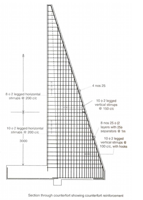
8. Counterfort
is a triangular shaped structure designed similar to a T-Beam as vertical
cantilever with varying depth (stem acts as flange). The main reinforcement is
along the sloping side. Stirrups are provided in the counterfort to secure them
firmly with the stem. Additional ties are provided to securely tie the
counterfort to the heel slab.
1) Design a suitable counterfort retaining
wall to support a leveled backfill of height 7.5m above ground level on the toe
side. Assume good soil for the foundation at a depth of 1.5m below ground
level. The SBC of soil is 170kN/m2 with unit weight as 16kN/m3.
The angle of internal
friction.Thecoefficientof isfriction ?between=30thesoil and concrete is 0.5.
Use M25 concrete and Fe415 steel.
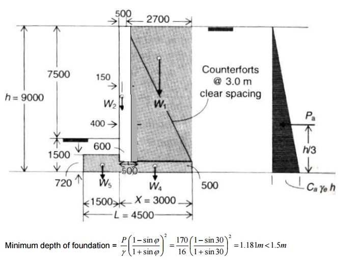
Depth of foundation = 1.5m
Height of wall =
7.5 + 1.5 = 9m
Thickness of heel
and stem =
5% of 9m
= 0.45m
Thickness of toe slab = 8%
of 9m = 0.72m
Lmin
= 1.5 x 3 = 4.5m
Thickness
of counterfort = 6% of 9 = 0.54m
Stability Condition:
Earth pressure calculations:
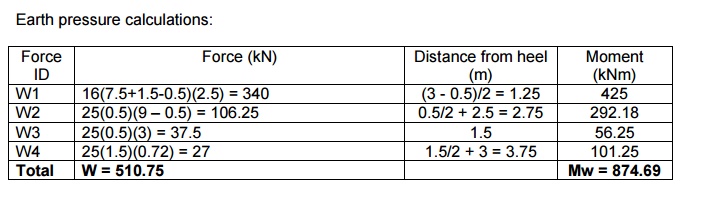
Xw = 874.69/510.75 = 1.713m
FOS (overturning) = 0.9Mr/Mo
Where
Mo = Pa.h/3 = Ca.e?.h3/6
= 0.33x16x93/6 = 647.35kNm.
Mr = (L -Xw).W = 510.75(4.5
-1.713) = 1423.6kNm.
FOS (overturning) = 1.98
> 1.4
Hence, section is safe against overturning.
Sliding:
FOS (sliding)
= 0.9(?R)/PaCos?
F = ?R
= 0.5 x
510.75 = 255.375kN
Pa = Ca.e?.h2/2
= 215.784
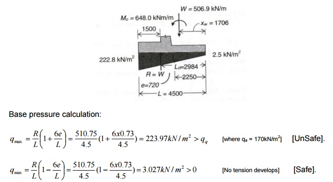
Where, LR = (M + Mo)/R,
e = LR -L/2, where, LR = (874.688 + 647.352)/510.75 =
2.98m
&
e = LR -L/2 = 2.98 -(4.5/2) = 0.73 < L/6 �
(0.75m)
Since the maximum earth pressure is greater
than SBC of soil, the length of base slab has to be increased preferably along
the toe side. Increase the toe slab by 0.5m in length.
?W = 510.75
+ 0.5 x
25 x 0.72
= 519.75kN
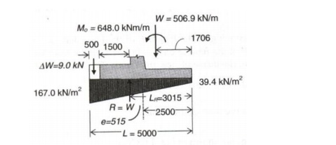
Additional load due to increase in toe slab
by 0.5m is, Moment = 0.5/2 + 4.5 = 4.75m
?M = 874.69
+ 42.75 =
917.438kNm.
LR = (Mo + M) / R = (917.438 + 647.352)/519.75 = 3.011m
e= LR -L/2 = 3.011 -(5/2) = 0.511m < L/6 - > (0.833m)
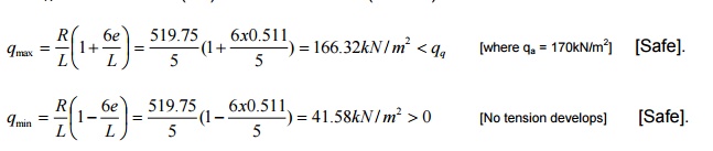
FOS (Sliding) = 0.9(?R)/Pa=0.9(0.5x519.75)/215.784
= 1.08 < 1.4.
Hence the section is not safe against
sliding. Shear key is provided to resist sliding. Assume shear key of size 300
x 300mm.
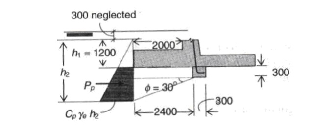
Pps = Cp.e?.(h22
-h12)/2 = 164.5kN/m
FOS (sliding) = 0.9(?Rps)/Pa =
+1.77P> 1.4 [where,
h1 = 1.2m, h2 = 1.2 + 0.3 + 1.39 = 2.88m]
Hence, section is safe in sliding with shear
key 300 x 300mm.

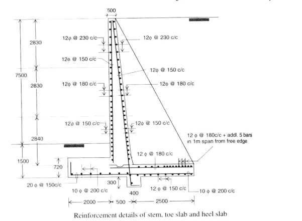
Design of Toe Slab:
Effective cover = 75 + 20/2 = 85mm
Toe slab is designed similar to cantilever
slab with maximum moment at front face of the stem and maximum shear
at�d?fromfront face of stem.
d = 720 -85 = 635mm.
M = 80.38x22/2 + � x 2 x 49.94 x
2/3 x 2 = 160.76 + 122.76 = 227.35kNm.
SF at 0.635m, = 49.94/2 x 0.635 = 15.606kN
Area of trapezoid = �.h.(a + b) = �(2
-0.635)(130.32 + 95.98) = 154.44kN
Factored SF = 231.66kN; Factored Moment =
341.02kNm.
K = Mu/bd2
� Ast = 1551.25mm2 � Spacing
= 1000ast/Ast � 16mm @125mmc/c.
Transverse reinforcement: = 0.12% of c/s
= 0.12/100 x 1000 x 720 = 864mm2
Provide 10mm @100mm c/c.
Design of heel slab:
The heel slab is designed as an one way
continuous slab with moment wl2/12 at the support and wl2/16
at the midspan. The maximum shear at the support is w(l/2 -d). The maximum
pressure at the heel slab is considered for the design.
Moment at the support, Msup = wl2/12
= 106.92 x 2.52/12 = 55.688kNm.
Moment at the midspan, Mmid = wl2/16
= 41.76kNm
The maximum
pressure acting on
the heelstrequiredslabat
midspan and support are found.
Factored Msup =
83.53kNm � Ast = 570.7mm2
Factored Mmid =
62.64kNm � Ast = 425.4mm2
Using
16mm ? bar,
Spacing �=Provide1000ast16mm@110mm/Astc/c
At midspan, spacing = 156.72mm � Provide 16mm @ 150mm c/c
Transverse reinforcement = 0.12% of c/s =
0.12/100 x 1000 x 500 = 600mm2
For 8mm bar, Spacing = 83.775mm �
Provide 8mm @80mm c/c.
Check for shear:
Maximum shear = w (l/2 -d) = 107 (2.5/2
-0.415) = 89.345kN
Factored shear force = 134.0175kN
?v = 0.33N/mm , ?c
= 0,.29N/mm?cmax =
3.1N/mm
Depth has to be increased. Design of stem:
The stem is also designed as
one way continuous slab with support moment wl2/12 and midspan
moment wl2/16. For the negative moment at the support, reinforcement
is provided at the rear side and for positive moment at midspan, reinforcement
is provided at front face of the stem.
The maximum moment varies from a base intensity of Ka.e?.h=1/3x16x(9-0.5)=
45.33kN/m Msup = wl2/12 = 1.5 x 45.33 x 3.542/12
= 71kNm
Mmid = wl2/16 = 1.5 x 45.33 x 3.542/16
= 53.26kNm Effective depth = 500 -(50 + 20/2) = 440mm
Ast at support = 1058mm2, For
16mm ?,190mmSpacing.Provide16mm
=@ 190mm c/c
Ast at midspan =718mm2, For 16mm
?,280mmSpacing.Provide16mm@280mm= c/c Max. SF = w (l/2 -d) = 60.29kN, Factored
SF = 90.44kN
Transverse reinforcement = 0.12% of c/s � 8mm @ 80mmc/c
?v = 0.188N/mm2,c
=?0.65N/mm2,cmax?= 3.1N/mm2 Safe in Shear. Design
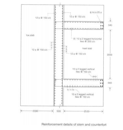
of Counterfort:
The counterfort is designed as a cantilever beam whose
depth is equal to the length of the heel slab at the base and reduces to the
thickness of the stem at the top. Maximum moment at the base of counterfort, Mmax
= Ka.e?.h3/6 x Le
Where, Le � c/c
distance from counterfort
Mmax = 1932.5kNm, Factored Mmax = 2898.75kNm
Ast = 2755.5mm2, Assume 25mm?bar,
No. of bars required = 2755.5/491.5 = 5.61 ~ 6 The main reinforcement is
provided along the slanting face of the counterfort. Curtailment of
reinforcement:
Not all the 6 bars need to be taken to the
free end. Three bars are taken straight to the entire span of the beam. One bar
is cut at a distance of, n -1/8.5 = h12/8.52 , where
n is the total number of bars and h1 is the distance from top. N
When n = 6, h1 = 7.75m [from bottom]
The second part is cut at a distance of,
n -2/ n = h2/8.52 , h2=6.94m [from bottom]
The third part is cut at a distance of,
n -3/ n = h32/8.52 , h3=6. 01m [from bottom]
Vertical ties and horizontal
ties are provided to connect the counterfort with the vertical stem and the
heel slab.
Design of horizontal ties:
Closed stirrups are provided
to the vertical stem and the counterfort. Considering 1m strip, the tension
resisted by reinforcement is given by lateral pressure on the wall multiplied
by contributing area.
T = Ca.e?.h x h, where, Ast = 1/ 0.87
fy
T = 1/3 x 16 x (9 -0.5) x 3.54 = 160.48kN Factored force,
T = 1.5 x 160.48kN
Ast = 666.72mm2. For 10mm ?,
Spacing110mm. =
Provide 10mm@110mm c/c closed stirrups as horizontal
ties. Design of vertical ties:
The vertical stirrup
connects the counterfort and the heel slab. Considering 1m strip, the tensile
force is the product of the average downward pressure and the spacing between
the counterforts. T = Avg(43.56 & 107) x Le = 266.49 kN
Factored
T = 399.74 kN
Ast = 1107.15mm2. For 10mm
?, Spacing70.93mm. =
Provide 10mm @ 70mm c/c.
Related Topics