Chapter: Mechanical and Electrical : Power Plant Engineering : Diesel,Gas Tubine and Combined Cycle Power Plants
Working of gas turbine cycle with inter cooling
Working of gas turbine cycle with
inter cooling
Net
work output from gas turbine cycle can also be increased by reducing negative
work i.e., compressor work. Multistaging of compression precess with
intercooling in between is one of the approaches for reducing compression work.
It is based on the fact that for a fixed compression ratio is higher is the
inlet temperature higher shall be compression work requirement and vice-versa.
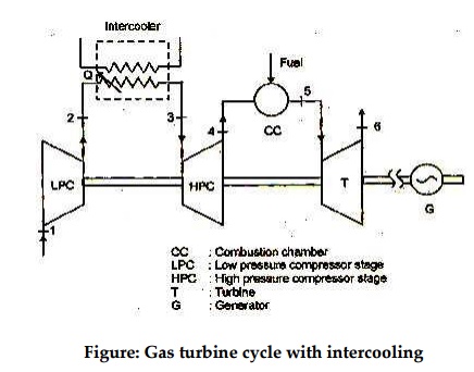
Schematic for inter cooled gas turbine cycle is give in figure.
Thermodynamic processes involved in multistage inter
cooled compression are shown in figure. First stage compression occurs in low
pressure compressor (LPC) and compressed air leaving LPC at ‘2’issent to
intercooler where temperature of compressed air is lowered down to state 3 at
constant pressure. In case of perfect intercooling the temperature after
intercooling is brought down to ambient temperature i.e., temperature at 3 and
1 are same. Intercooler is a kind of heat exchanger where heat is picked up
from high temperature compressed air. The amount of compression work saved due
to intercooling is obvious from p-V diagram and shown by area 2342’Area.
2342’givestheamount of work saved due to intercooling between compression.
Figure: Gas turbine cycle with
intercooling
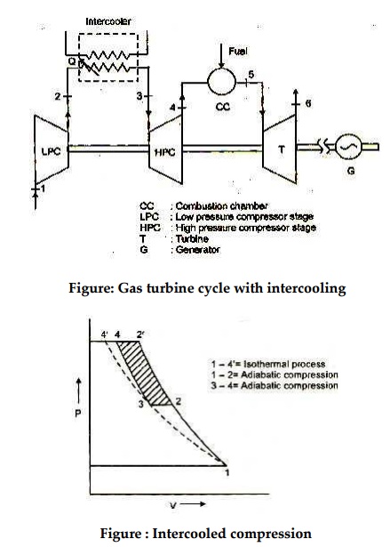
Figure : Intercooled compression
Some
large compressors have several stages of compression with intercooling between
stages. Use of multistage compression with intercooling in a gas turbine power
plant increases the network produced because of reduction in compressor work.
Inter cooled compression results in reduced temperature at the end of final
compression. T-S diagram for gas turbine cycle with intercooling shows that in
the absence of intercooling within same pressure limits the state at the end of
compression would be 2’while with perfect intercooling this state is at 4 i.e.,
T2’> T4. The reduced temperature at compressor exits leads to additional
heat requirement in combustion chamber i.e., more amount of fuel is to be burnt
for attaining certain inlet temperature as compared to simple cycle without
intercooling.
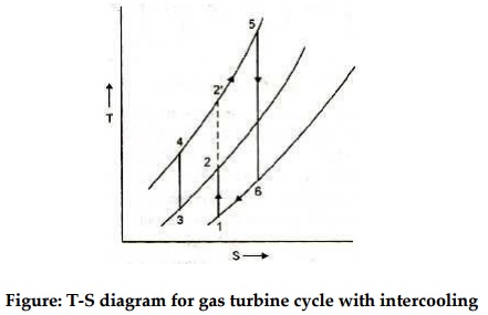
Figure: T-S diagram for gas turbine
cycle with intercooling
Thus
intercooled cycle thermal efficiency may not increase with intercooling because
of simultaneous increase in heat addition requirement. The lower temperature at
compressor exit enhances the potential for regeneration so when intercooling is
used in conjunction with regeneration an appreciable increase in thermal
efficiency can result.
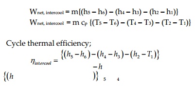
Net work output in gas turbine cycle
with intercooling;
Wnet, intercool = m{(h5 –h6) –(h4 –h3)
–(h2 –h1)}
Wnet, intercool = m cp {(T5 –T6) –(T4 –T3) –(T2 –T1)}
Related Topics