Chapter: Electronic Circuits : Blocking Oscillators and Timebase Generators
Unijunction Sawtooth Generator
Unijunction Sawtooth Generator
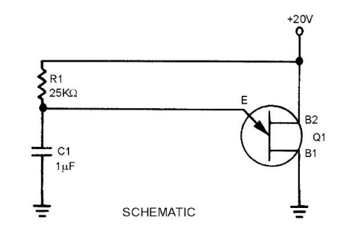
When the 20 volts is applied across B2 and B1,
the n-type bar acts as a voltage- divider. A voltage of 12.8 volts appears at a
point near the emitter. At the first instant, C1 has no voltage across it, so
the output of the circuit, which is taken across the capacitor (C1), is equal
to 0 volts. (The voltage across C1 is also the voltage that is applied to the
emitter of the unijunction.)
The unijunction is now reverse biased. After
T0, C1 begins to charge toward 20 volts.At T1, the voltage across the capacitor
(the voltage on the emitter) has reached approximately 12.8 volts. This is the
peak point for the unijunction, and it now becomes forward biased.
With the emitter forward biased, the impedance
between the emitter and B1 is just a few ohms. This is similar to placing a
short across the capacitor. The capacitor discharges very rapidly through the
low resistance of B1 to E.
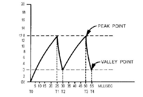
As C1 discharges, the voltage from the emitter
to B1 also decreases. Q1 will continue to be forward biased as long as the
voltage across C1 is larger than the valley point of the unijunction. At T2 the
3-volt valley point of the unijunction has been reached. The emitter now
becomes reverse biased and the impedance from the emitter to B1 returns to a
high value. Immediately after T2, Q1 is reverse biased and the capacitor has a
charge of approximately 3 volts. C1 now starts to charge toward 20 volts as it
did originally.
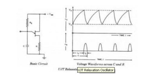
The circuit operation from now on is just a
continuous repetition of the actions between T2 and T4.The capacitor charges
until the emitter becomes forward biased, the unijunction conducts and
C1discharges, and Q1 becomes reverse biased and C1 again starts charging.
Now, let's determine the linearity, electrical
length, and amplitude of the output waveform. First, the linearity: To charge
the circuit to the full 20 volts will take 5 time constants. In the circuit
shown in figure 3-44, view (B), C1 is allowed to charge from T2 to T3. To find
the percentage of charge, use the equation:
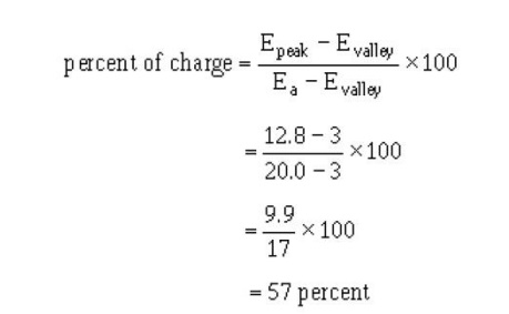
This works out to be about 57 percent and is
far beyond the 10 percent required for a linear sweep voltage.
Related Topics