Chapter: Measurements and Instrumentation : Electrical and Electronics Instruments
Types of Digital Voltmeter(DVM)
Digital Voltmeter
A digital voltmeter (DVM) displays the value of a.c. or d.c. voltage being measured directly as discrete numerals in the decimal number system. Numerical readout of DVMs is advantageous since it eliminates observational errors committed by operators.
The errors on account of parallax and approximations are entirely eliminated. The use of digital voltmeters increases tile speed with which readings can be taken.
A digital voltmeter is a versatile and accurate voltmeter which has many laboratory applications.
On account of developments in the integrated circuit (IC) technology, it has been possible to reduce the size, power requirements and cost of digital voltmeters.
In fact, for the same accuracy, a digital voltmeter now is less costly than its analog counterpart.
The decrease in size of DVMs on account of use of ICs, the portability of the instruments has increased.
Types of DVMs
The increasing popularity of DVMs has brought forth a wide number of types employing different circuits. The various types of DVMs in general use are
(i) Ramp type DVM
(ii) Integrating type DVM
(iii) Potentiometric type DVM
(iv) Successive approximation type DVM
(v) Continuous balance type DVM
i. Ramp type Digital Voltmeter
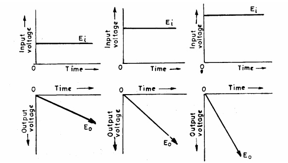
The operating principle of a ramp type digital voltmeter is to measure the time that a linear ramp voltage takes to change from level of input voltage to zero voltage (or vice versa).This time interval is measured with an electronic time interval counter and the count is displayed as a number of digits on electronic indicating tubes of the output readout of the voltmeter. The conversion of a voltage value of a time interval is shown in the timing diagram .A negative going ramp is shown in Fig. but a positive going ramp may also be used. The ramp voltage value is continuously compared with the voltage being measured (unknown voltage).At the instant the value of ramp voltage is equal to that of unknown voltage. The ramp voltage continues to decrease till it reaches ground level (zero voltage).At this instant another comparator called ground comparator generates. a pulse and closes the gate. The time elapsed between opening and closing of the gate is t as indicated in Fig. During this time interval pulses from a clock pulse generator pass through the gate and are counted and displayed. The decimal number as indicated by the readout is a measure of the value of input voltage. The sample rate multivibrator determines the rate at which the measurement cycles are initiated. The sample rate circuit provides an initiating pulse for the ramp generator to start its next ramp voltage.
At the same time it sends a pulse to the counters which set all of them to 0. This momentarily removes the digital display of the readout.
ii. Integrating Type Digital Voltmeter
The voltmeter measures the true average value of the input voltage over a fixed measuring period. In contrast the ramp type DVM samples the voltage at the end of the measuring period. This voltmeter employs an integration technique which uses a voltage to frequency conversion. The voltage to frequency (VIF) converter functions as a feedback control system which governs the rate of pulse generation in proportion to the magnitude of input voltage.
Actually when we employ the voltage to frequency conversion techniques, a train of pulses, whose frequency depends upon the voltage being measured, is generated.
Then the number of pulses appearing in a definite interval of time is counted.
Since the frequency of these pulses is a function of unknown voltage, the number of pulses counted in that period of time is an indication of the input (unknown) voltage.
The heart of this technique is the operational amplifier acting as an Integrator. Output voltage of integrator E = -Ei / RC*t
Thus if a constant input voltage E is applied, an output voltage E is produced which rises at a uniform rate and has a polarity opposite to that input voltage.
In other words, it is clear from the above relationship that for a constant input voltage the integrator produces a ramp output voltage of opposite polarity.
The basic block diagram of a typical integrating type of DVM is shown in
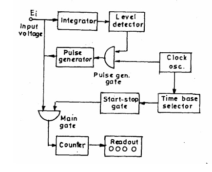
The unknown voltage is applied to the input of the integrator, and the output voltage starts to rise. The slope of output voltage is determined by the value of input voltage This voltage is fed a level detector, and when voltage reaches a certain reference level, the detector sends a pulse to the pulse generator gate. The level detector is a device similar to a voltage comparator. The output voltage from integrator is compared with the fixed voltage of an internal reference source, and, when voltage reaches that level, the detector produces an output pulse.
It is evident that greater then value of input voltage the sharper will be the slope of output voltage and quicker the output voltage will reach its reference level.
The output pulse of the level detector opens the pulse level gate, permitting pulses from a fixed frequency clock oscillator to pass through pulse generator.
The generator is a device such as a Schmitt trigger that produces an output pulse of fixed amplitude and width for every pulse it receives. This output pulse, whose polarity is opposite to that of and has greater amplitude, is fedback of the input of the integrator. Thus no more pulses from the clock oscillator can pass through to trigger the pulse generator. When the output voltage pulse from the pulse generator has passed, is restored to its original value and starts its rise again. When it reaches the level of reference voltage again, the pulse generator gate is opened. The pulse generator is trigger by a pulse from the clock generator and the entire cycle is repeated again.
Thus, the waveform of is a saw tooth wave whose rise time is dependent upon the value of output voltage and the fail time is determined by the width of the output pulse from the pulse generator. Thus the frequency of the saw tooth wave is a function of the value of the voltage being measured. Since one pulse from the pulse generator is produced for each cycle of the saw tooth wave, the number of pulses produced in a given time interval and hence the frequency of saw tooth wave is an indication of the voltage being measured.
iii. Potentiometric Type Digital Voltmeter
A potentiometric type of DVM employs voltage comparison technique. In this DVM the unknown voltage is compared with reference voltage whose value is fixed by the setting of the calibrated potentiometer.
The potentiometer setting is changed to obtain balance (i.e. null conditions).
When null conditions are obtained the value of the unknown voltage, is indicated by the dial setting of the potentiometer.
In potentiometric type DVMs, the balance is not obtained manually but is arrived at automatically.
Thus, this DVM is in fact a self- balancing potentiometer.
The potentiometric DVM is provided with a readout which displays the voltage being measured.
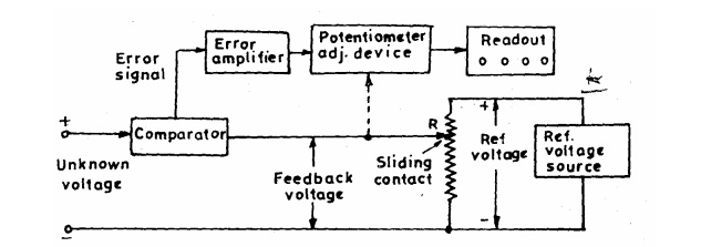
The block diagram of basic circuit of a potentiometric DVM is shown. The unknown voltage is filtered and attenuated to suitable level. This input voltage is applied to a comparator (also known as error detector).This error detector may be chopper. The reference voltage is obtained from a fixed voltage source. This voltage is applied to a potentiometer. The value of the feedback voltage depends up the position of the sliding contact. The feedback voltage is also applied to the comparator. The unknown voltage and the feedback voltages are compared in the comparator. The output voltage of the comparator is the difference of the above two voltages. The difference of voltage is called the error signal. The error signal is amplified and is fed to a potentiometer adjustment device which moves the sliding contact of the potentiometer. This magnitude by which the sliding contact moves depends upon the magnitude of the error signal.
The direction of movement of slider depends upon whether the feedback voltage is larger or the input voltage is larger. The sliding contact moves to such a place where the feedback voltage equals the unknown voltage. In that case, there will not be any error voltage and hence there will be no input to the device adjusting the position of the sliding cont act and therefore it (sliding contact) will come to rest. The position of the potentiometer adjustment device at this point is indicated in numerical form on the digital readout device associated with it.
Related Topics