Chapter: Measurements and Instrumentation : Electrical and Electronics Instruments
Instrument Transformers

Instrument
Transformers
Power
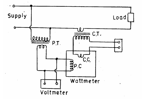
measurements are made in high voltage circuits connecting the wattmeter to the
circuit through current and potential transformers as shown.
The
primary winding of the C.T. is connected in series with the load and the
secondary winding is connected in series with an ammeter and the current coil
of a wattmeter.
The
primary winding of the potential transformer is connected across the supply
lines and a voltmeter and the potential coil circuit of the wattmeter are
connected in parallel with the secondary winding of the transformer. One
secondary terminal of each transformer and the casings are earthed.
The
errors in good modem instrument transformers are small and may be ignored for
many purposes.
However,
they must be considered in precision work. Also in some power measurements
these errors, if not taken into account, may lead to very inaccurate results.
Voltmeters
and ammeters are effected by only ratio errors while wattmeters are influenced
in addition by phase angle errors. Corrections can be made for these errors if
test information is available about the instrument transformers and their
burdens.
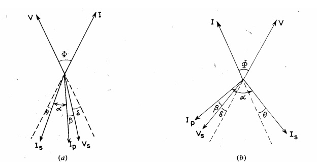
Phasor
diagrams for the current and voltages of load, and in the wattmeter coils.
Related Topics