Chapter: Measurements and Instrumentation : Electrical and Electronics Instruments
Magnetic Measurements

MAGNETIC MEASUREMENTS
The operating characteristics of electrical machines, apparatus and instruments are greatly influenced by the properties of Ferro-magnetic materials used for their construction. Therefore, magnetic measurements and a thorough knowledge of characteristics of magnetic materials are of utmost importance in designing and manufacturing electrical equipment.
The principal requirements in magnetic measurements are
(i) The measurement of magnetic field strength in air.
(ii) The determination of B-H curve and hysteresis loop for soft Ferro-magnetic materials.
(iii) The determination of eddy current and hysteresis losses of soft Ferro-
magnetic materials subjected to alternating magnetic fields.
(iv) The testing of permanent magnets.
Magnetic measurements have some inherent inaccuracies due to which the measured values depart considerably from the true values. The inaccuracies are due to the following reasons
(i) The conditions in the magnetic specimen under test are different from those assumed in calculations;
(ii) The magnetic materials are not homogeneous
(iv)There is no uniformity between different batches of test specimens even if such batches are of the same composition.
Types of Tests
Many methods of testing magnetic materials have been devised wherein attempts have been made to eliminate the inaccuracies. However, attention will be confined to a few basic methods of ‘ Testing Ferro-magnetic materials. They are:
(i) Ballistic Tests: These tests are generally employed for the determination of B- H curves and hysteresis loops of Ferro-magnetic materials.
(ii) A. C. Testing. These tests may be carried at power, audio or radio frequencies. They give information about eddy current and hysteresis losses in magnetic materials.
(iii) Steady State Tests. These are performed to obtain the steady value of flux density existing in the air gap of a magnetic circuit.
Ballistic Tests: These tests are used for determination of flux density in a specimen, determination of B-H curves and plotting of hysteresis loop.
Measurement of Flux Density
The measurement of flux density inside a specimen can be done by winding a search coil over the specimen.
This search coil is known as a “ B coil” .
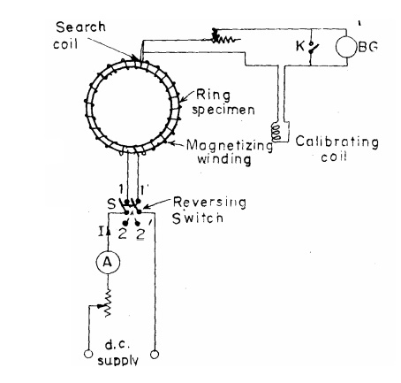
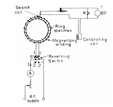
This search coil is then connected to a ballistic galvanometer or to a flux meter. Let us consider that we have to measure the flux density in a ring specimen shown in Fig.
The ring specimen is wound with a magnetizing winding which carries a current I.
A search coil of convenient number of turns is wound on the specimen and connected through a resistance and calibrating coil, to a ballistic galvanometer as shown.
The current through the magnetizing coil is reversed and therefore the flux linkages of the search coil change inducing an emf in it.
Thus emf sends a current through the ballistic galvanometer causing it to deflect.

Magnetic Potentiometer
This is a device for measurement of magnetic potential difference between two points.
It can be shown that the line integral of magnetizing force H produced by a coil of N concentrated turns carrying a current I is:

around any closed path linking the coil.

This is the circuital law of the magnetic field and forms the basis of magnetic potentiometer.
A magnetic potentiometer may be used to determine the mmf around a closed path, or the magnetic potential difference between two points in a magnetic circuit.
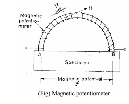
A magnetic potentiometer consists of a one metre long flat and uniform coil made of two or four layers of thin wire wound unidirectional on a strip of flexible non-magnetic material.
The coil ends are brought out at the middle of the strip as shown in Fig. and connected to a ballistic galvanometer.
The magnetic potential difference between points A and B of the field is measured by placing the ends of the strip at these points and observing the throw of the ballistic galvanometer when the flux through the specimen is changed.
Related Topics