Chapter: Electrical Engineering and Instrumentation : DC Machines
Theory of Operation of DC Generators
Theory of Operation Of DC Generators
A generator works on the principles of Faraday’s law of electromagnetic induction.
It states that “Whenever a conductor is moved in the magnetic field, an emf is induced andthe magnitude of the induced emf is directly proportional to the rate of change of flux linkage”. This emf causes a current flow if the conductor circuit is closed.
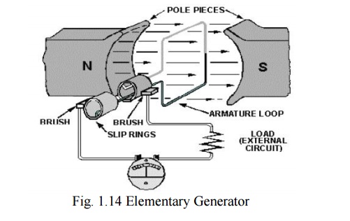
The pole pieces (marked N and S) provide the magnetic field. The pole pieces are shaped and positioned as shown above to concentrate the magnetic field as close as possible to the wire loop. The loop of wire that rotates through the field is called the ARMATURE. The ends of the armature loop are connected to rings called SLIP RINGS. They rotate with the armature. The brushes, usually made of carbon, with wires attached to them, ride against the rings. The generated voltage appears across these brushes.
The elementary generator produces a voltage in the following manner.
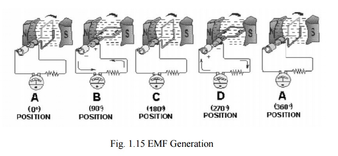
The armature loop is rotated in a clockwise direction. The initial or starting point is shown at position A. (This will be considered the zero-degree position.) At 0º the armature loop is perpendicular to the magnetic field. The black and white conductors of the loop are moving parallel to the field. The instant the conductors are moving parallel to the magnetic field, they do not cut any lines of flux. Therefore, no emf is induced in the conductors, and the meter at position A indicates zero. This position is called the NEUTRAL PLANE.
As the armature loop rotates from position A (0º) to position B (90º), the conductors cut through more and more lines of flux, at a continually increasing angle. At 90º they are cutting through a maximum number of lines of flux and at maximum angle. The result is that between 0º and 90º the induced emf in the conductors builds up from zero to a maximum value. Observe that from 0º to 90º the black conductor cuts DOWN through the field. At the same time the white conductor cuts UP through the field. The induced emfs in the conductors are series-adding. This means the resultant voltage across the brushes (the terminal voltage) is the sum of the two induced voltages. The meter at position B reads maximum value.
As the armature loop continues rotating from 90º (position B) to 180º (position C), the conductors which were cutting through a maximum number of lines of flux at position B now cut through fewer lines. They are again moving parallel to the magnetic field at position C. They no longer cut through any lines of flux. As the armature rotates from 90º to 180º, the induced voltage will decrease to zero in the same manner that it increased during the rotation from 0º to 90º. The meter again reads zero. From 0º to 180º the conductors of the armature loop have been moving in the same direction through the magnetic field. Therefore, the polarity of the induced voltage has remained the same. This is shown by points A through C on the graph.
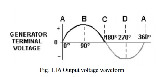
As the loop rotates beyond 180º (position C), through 270º (position D), and back to the initial or starting point (position A), the direction of the cutting action of the conductors through the magnetic field reverses. Now the black conductor cuts UP through the field while the white conductor cuts DOWN through the field. As a result, the polarity of the induced voltage reverses. Following the sequence shown by graph points C, D, and back to A, the voltage will be in the direction opposite to that shown from points A, B, and C. The terminal voltage will be the same as it was from A to C except that the polarity is reversed (as shown by the meter deflection at position D). The voltage output waveform for the complete revolution of the loop is shown in figure 1.16.
EMF Equation of Generator
Let
Φ = flux/pole in webers
Z = total number of armature connductors
= No. of slots x No. of conductors/slot P = No. of poles
A = No. of parallel paths in armature
N = Armature rotation in revolutions per minute (r.p.m)
E = e.m.f induced in any parallel path in armature
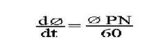
Average e.m.f generated /conduc tor = dΦ/dt volt (n=1)
Now, flux cut/conductor in one revolution dΦ = ΦPWb
No. of revolutions/second = N/6 0
Time for one revolution, dt = 60/N second
According to Faraday's Laws of Electromagnetic Induction,
E.M.F generated/conductor is
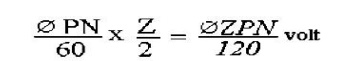
For a simplex wave-wound gen erator
No. of parallel paths = 2
No. of conductors (in series) in o ne path = Z/2
E.M.F. generated/path is
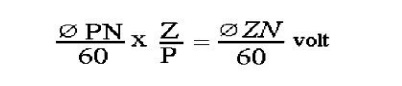
For a simplex lap-wound generator
No. of parallel paths = P
No. of conductors (in series) in o ne path = Z/P
E.M.F.generated/path
In general generated e.m.f
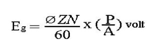
Where, A = 2 for simplex wave- winding.
A = P for simplex lap-w inding.
Related Topics