Chapter: Civil : Principles of Solid Mechanics : Introduction
Symmetric and Asymmetric Components
Symmetric and
Asymmetric Components
Any tensor can be resolved into symmetric
and asymmetric components where symmetry or asymmetry is with respect to the
diagonal. That is,
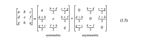
each of which have quite a different physical
effect.
Asymmetric
Transformation
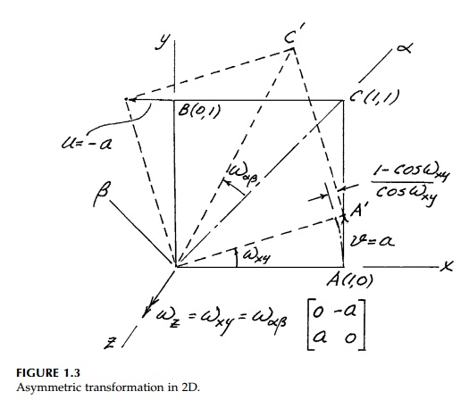
Consider first the displacement due to
an asymmetric tensor such as:
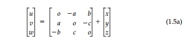
It can be shown to produce a rotation ?=
tan-1 Rt(a2
+
b2 +
c2 ) 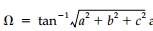 around an axis whose direction ratios are a, b, and c
plus a dilation (a change in size, but not shape). To illustrate, consider the
unit square in the x, y plane with b = c = 0
around an axis whose direction ratios are a, b, and c
plus a dilation (a change in size, but not shape). To illustrate, consider the
unit square in the x, y plane with b = c = 0
As shown in Figure 1.3,
all points rotate in the xy plane an angle ?= tan -1 a
around the z axis positive in that the rotation vector is in the
positive z direction by the right-hand screw rule. Thus the rotation is
independent of orientation of the axes in the xy plane and therefore
'invariant.' That is ?xy=?ab and the sym-bol ?z
for the rotation vector is sensible although ?xy is more
common in the literature. For 'small' rotations, ?z =
a and the isotropic dilation ( -1 + 1/cos a) is
negligible.
Similarly, b and c
represent rotation around the y and x axes, respectively.
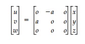
Therefore, the asymmetric displacement tensor can be rewritten
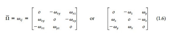
The rotation is not a
tensor of second order, but a vector ?Bar = ?xi +
?yj + ?zk
made up of three invariant scalar magnitudes in the subscripted directions.
![]()
Symmetric
Transformation
The symmetric component of a linear
displacement tensor can similarly be understood by simple physical examination
of the individual elements. Con-sider first the diagonal terms a, b,
and c in the symmetric tensor:
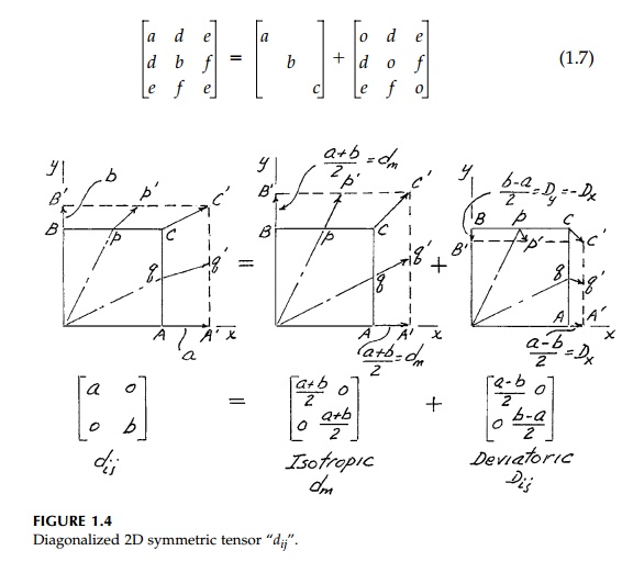
Clearly they produce expansion
(contraction if negative) in the xyz directions proportional to the
distance from the origin. The 2D case is shown in Figure 1.4, which also
illustrates how the effect of the diagonal terms can be further decomposed into
two components that are distinctly different physically. In 3D:
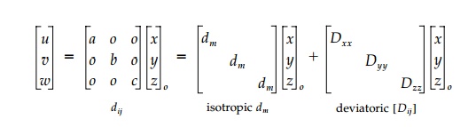
where the isotropic component producing
pure volume change and no distortion is actually a scalar (tensor of order
zero) in which dm = a + b + c / 3. The so-called deviatoric component terms:
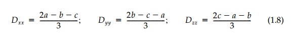
sum to zero and produce
pure distortion and secondary volume change.* For 'small' displacements, the
volume change, ?V, is simply 3dm and the deviatoric
volume change is negligible. The subscript, o, is to emphasize the
linear superposition is valid for large displacements only if the components
are successively applied to the original position vector (base lengths)
as is customary in engineering.
Returning to Figure 1.4, it might appear
that since individual points (or lines) such as p, q, or c
rotate, the deviatoric component is rotational. This is not true and, in fact,
symmetric transformations are also called irrotational (and reciprocal). This
is illustrated in Figure 1.5 where the diagonal deviatoric transformation
components, Dij, of Figure 1.4 are applied to the second
quadrant as well as
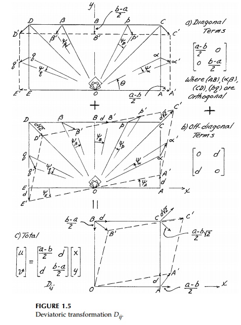
the first (plotted at
twice the scale for clarity). The lower two quadrants would be similar.
Thus, line rotations
are compensating and there is no net rotation of any pair of orthogonal
directions (such as xy, pq, ??, or CD) or for any
reflected pair of lines. Any square element, since it is bounded by
orthogonal lines, does not rotate either and, for small displacements, its
volume will not change. It will undergo pure distortion (change in shape).
Certain lines (directions) do not rotate in themselves (in this case, xy)
and are termed principal directions while those 45 o from them (OC and OD),
undergo the maximum compensating angle change.* The angle change itself (in
radians) is called the shear and is consid-ered positive if the 90 o angle at
the origin decreases.
Now consider the
off-diagonal symmetric terms. The 2D case is shown in Figure 1.5b. Again there
is distortion of the shape and, therefore, the off-diagonal symmetric terms are
also deviatoric (shear). In this case the lines that do not rotate (principal)
are the C-D orthogonal pair and maximum rotation is in the x-y
orientation. Thus, again, the maximum and minimum are 45 o apart,
just as they were for the diagonal deviatoric terms. In fact, it is easy
to show that the diagonal and the off-diagonal terms produce the identical
physical effect 45 o out
of phase if b-a/2=d.
With either set of deviatoric terms, diagonal or off-diagonal, the element
expands in one direction while it contracts an equal amount at right angles. If
the element boundaries are not in the principal directions, they rotate in
compensating fashion and square shapes become rhomboid. The combined effects on
an element of the total deviatoric component is shown in Figure 1.5c. Any
isotropic component would simply expand or contract the element.
Extension to 3D is straightforward
conceptually, but difficult to draw. The components of the general 3D symmetric
transformation will be reviewed in terms of strain and fully defined in terms
of stress in the next pages.
Related Topics