Chapter: Civil : Principles of Solid Mechanics : Introduction
Finite Linear Transformation
Finite Linear
Transformation
When a body is loaded, the original coordinates of all the points move to a new position. The movement of each point A, B, or C to A'B'C' in Figure 1.1 is the movement of the position vectors r1 , r2 , and (r1 Bar r2 Bar) where we assume a common origin. A linear transforation is defined as one that transforms vec-tors according to the rules.*
where [a] is the 'finite linear
transformation tensor.' Also,

and:
a. straight
lines remain straight
b. parallel
lines remain parallel
c. parallel
planes remain parallel
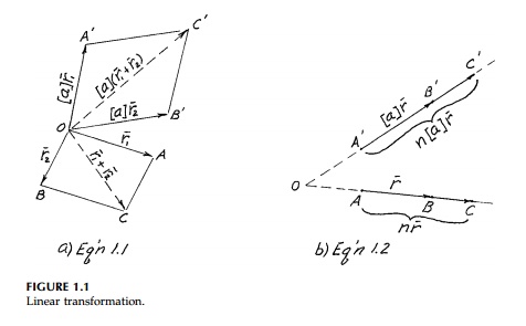
Equations (1.1) and
(1.2) are illustrated in Figures 1.1(a) and (b) where n is some
constant.
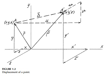
Consider a point A, with
Cartesian coordinates x, y, z, which can be thought of as
a position or radius vector from the origin as in Figure 1.2. This
vector can be written
On linear transformation, this point
moves to a new position A' with new coordinates x',
y',
z'.
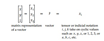
This transformation can be written in various forms as
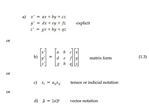
Of these, a and b
are the most cumbersome and time consuming to use but they are graphic. They
emphasize that we are simply dealing with simulta-neous equations. Moreover,
they are global and, if linear, the coefficients [a] which are
the components of a real, physical transformation tensor must be constant and
not themselves functions of x, y, z since if any of the
coefficients involve x, y, or z, the equations would have
cross products or powers of x, y, z and be nonlinear.
Tensor or indicial notation is the most efficient, but only after years of
writing out the implied equations does one get a physical feel for this
powerful shorthand.
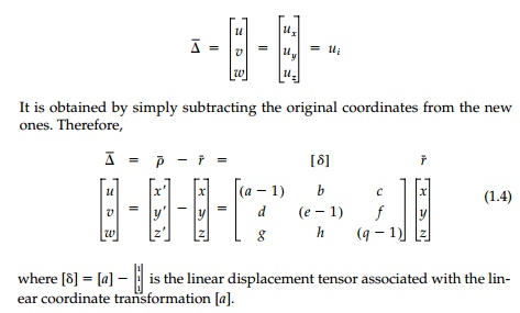
Instead of transforming coordinates of a
point (position vectors), it is usu-ally more fruitful in mechanics to talk
about how much the coordinates change (i.e., the movement of the tip of the
position vector). In fact, it will turn out that if we can find the movement or
displacement of all the points of a body, we can easily determine all the
strains and usually the stresses caus-ing them. As seen in Figure 1.2, the
displacement vector Del Bar of point A
moving to A' has components in the x,
y, z directions, which are usually called u, v, w
in engineering. That is,
Related Topics