Chapter: Mechanical and Electrical : Thermal Engineering : Steam Nozzles and Turbines
Steam Nozzles and Turbines
STEAM NOZZLES AND TURBINES
PREREQUISITE DISCUSSIONS
A steam
turbine is basically an assembly of nozzles fixed to a stationary casing and
rotating blades mounted on the wheels attached on a shaft in a row-wise manner.
In 1878, a Swedish engineer, Carl G. P. de Laval developed a simple impulse
turbine, using a convergent-divergent (supersonic) nozzle which ran the turbine
to a maximum speed of 100,000 rpm. In 1897 he constructed a velocity-compounded
impulse turbine (a two-row axial turbine with a row of guide vane stators
between them.
Auguste
Rateau in France started experiments with a de Laval turbine in 1894, and
developed the pressure compounded impulse turbine in the year 1900.
In the
USA , Charles G. Curtis patented the velocity compounded de Lavel turbine in
1896 and transferred his rights to General Electric in 1901.
In
England , Charles A. Parsons developed a multi-stage axial flow reaction
turbine in
1884.
Steam
turbines are employed as the prime movers together with the electric generators
in thermal and nuclear power plants to produce electricity. They are also used
to propel large ships, ocean liners, submarines and to drive power absorbing
machines like large compressors, blowers, fans and pumps.
Turbines
can be condensing or non-condensing types depending on whether the back
pressure is below or equal to the atmosphere pressure.
STEAM NOZZLE
Introduction
A steam
turbine converts the energy of high-pressure, high temperature steam produced
by a steam generator into shaft work. The energy conversion is brought about in
the following ways:
1. The
high-pressure, high-temperature steam first expands in the nozzles emanates as
a high velocity fluid stream.
2. The high
velocity steam coming out of the nozzles impinges on the blades mounted on a
wheel. The fluid stream suffers a loss of momentum while flowing past the
blades that is absorbed by the rotating wheel entailing production of torque.
3. The
moving blades move as a result of the impulse of steam (caused by the change of
momentum) and also as a result of expansion and acceleration of the steam
relative to them. In other words they also act as the nozzles.
Flow Through Nozzles
Ø A nozzle
is a duct that increases the velocity of the flowing fluid at the expense of
pressure drop.
Ø A duct
which decreases the velocity of a fluid and causes a corresponding increase in
pressure is a diffuser .
Ø The same
duct may be either a nozzle or a diffuser depending upon the end conditions
across it. If the cross-section of a duct decreases gradually from inlet to
exit, the duct is said to be convergent.
Ø Conversely
if the cross section increases gradually from the inlet to exit, the duct is
said to be divergent.
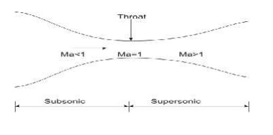
Ø If the
cross-section initially decreases and then increases, the duct is called a
convergent-divergent nozzle.
Ø The
minimum cross-section of such ducts is known as throat.
Ø A fluid
is said to be compressible if its density changes with the change in
pressure brought about by the flow.
Ø If the
density does not changes or changes very little, the fluid is said to be
incompressible. Usually the gases and vapors are compressible, whereas liquids
are incompressible .
Shapes of nozzles
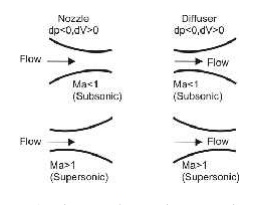
1. At
subsonic speeds (Ma<1) a decrease in area increases the speed of flow.
2. In
supersonic flows (Ma>1), the effect of area changes are different.
Convergent divergent nozzles
SIGNIFICANCE OF STEAM
TURBINES
Ø Large
scale electrical energy production largely depends on the use of turbines.
Nearly all of the world's power that is supplied to a major grid is produced by
turbines.
Ø From
steam turbines used at coal-burning electricity plants to liquid water turbines
used at hydro-electric plants, turbines are versatile and can be used in a
number of applications.
Ø There are
also gas turbines that combust natural gas or diesel fuel for use in remote
locations or where a large backup power supply is required. Most power plants
use turbines to produce energy by burning coal or natural gas.
Ø The heat
produced from combustion is used to heat water in boiler. The liquid water is
converted to steam upon heating and is exhausted through a pipe which feeds the
steam to the turbine.
Ø The
pressurized steam flow imparts energy on the blades and shaft of the turbine
causing it to rotate.
Ø The
rotational mechanical energy is then converted to electrical energy using a
generator.
STEAM TURBINES
Turbines
Ø We shall
consider steam as the working fluid
Ø Single
stage or Multistage
Ø Axial or
Radial turbines
Ø Atmospheric
discharge or discharge below atmosphere in condenser
Ø Impulse/and
Reaction turbine
Impulse Turbines
Ø Impulse
turbines (single-rotor or multirotor) are simple stages of the turbines.
Ø Here the
impulse blades are attached to the shaft.
Ø Impulse
blades can be recognized by their shape.
Ø The
impulse blades are short and have constant cross sections.
Schematic diagram of an
Impulse Trubine
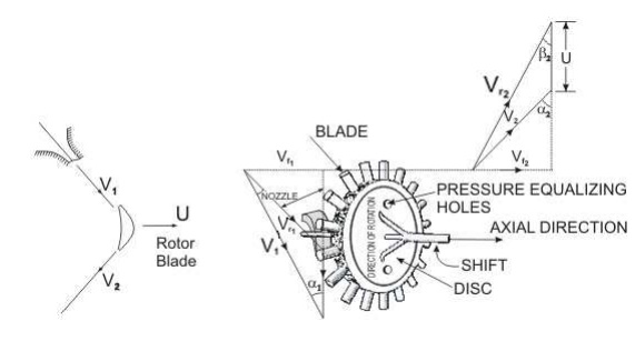
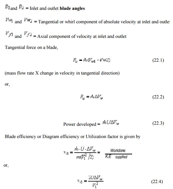
V1 and V2 = Inlet
and outlet absolute velocity
Vr1 and V r2 = Inlet and
outlet relative velocity (Velocity relative to the rotor blades.)
U = mean blade speed
= nozzle angle,
=
absolute
fluid angle at outlet
It is to be mentioned that all
angles are with respect to the tangential velocity ( in the direction of U )
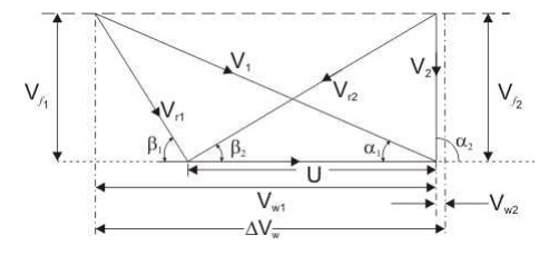
Velocity diagram of an
Impulse Turbine
The Single-Stage Impulse
Turbine
Ø The single-stage
impulse turbine is also called the de Laval turbine after its
inventor.
Ø The
turbine consists of a single rotor to which impulse blades are attached.
Ø The steam
is fed through one or several convergent-divergent nozzles which do not extend
completely around the circumference of the rotor, so that only part of the
blades is impinged upon by the steam at any one time.
Ø The
nozzles also allow governing of the turbine by shutting off one or more them.
Compounding in Impulse
Turbine
Ø If high
velocity of steam is allowed to flow through one row of moving blades, it
produces a rotor speed of about 30000 rpm which is too high for practical use.
Ø It is
essential to incorporate some improvements for practical use and also to
achieve high performance.
Ø This is
called compounding.
Ø Two types
of compounding can be accomplished: (a) velocity compounding and (b) pressure
compounding
The Velocity - Compounding
of the Impulse Turbine
Ø The
velocity-compounded impulse turbine was first proposed to solve the problems of
a single-stage impulse turbine for use with high pressure and temperature
steam.
Ø It is
composed of one stage of nozzles as the single-stage turbine, followed by two
rows of moving blades instead of one.
Ø These two
rows are separated by one row of fixed blades attached to the turbine stator,
which has the function of redirecting the steam leaving the first row of moving
blades to the second row of moving blades.
Pressure Compounding or
Rateau Staging
Ø To
alleviate the problem of high blade velocity in the single-stage impulse
turbine, the total enthalpy drop through the nozzles of that turbine are simply
divided up, essentially in an equal manner, among many single-stage impulse
turbines in series,Such a turbine is called a Rateau turbine.
Ø The
inlet steam velocities to each stage are essentially equal and due to a reduced
Δh.
Reaction Turbine
Ø A reaction
turbine, therefore, is one that is constructed of rows of
fixed and rows of moving blades.
Ø The fixed
blades act as nozzles.
Ø The
moving blades move as a result of the impulse of steam received (caused by
change in momentum) and also as a result of expansion and acceleration of the
steam relative to them.
Ø The
pressure drops will not be equal.
Ø They are
greater for the fixed blades and greater for the high-pressure than the
low-pressure stages.
Ø The
absolute steam velocity changes within each stage as shown and repeats from
stage to stage.
APPLICATIONS
Ø Locomotives
Ø Power
generations
Ø Industrial
application for producing steam
Governing of Steam Turbine: The
method of maintaining the turbine speed constant irrespective of the
load is known as governing of turbines. The device used for governing of
turbines is called Governor. There are 3 types of governors in steam turbine,
1. Throttle
governing
2. Nozzle
governing
3. By-pass
governing
i.Throttle Governing:
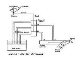
Let us consider an instant when the load on the
turbine increases, as a result the speed of the turbine decreases. The fly
balls of the governor will come down. The fly balls bring down the sleeve. The
downward movement of the sleeve will raise the control valve rod. The mouth of
the pipe AA will open. Now the oil under pressure will rush from the control
valve to right side of piston in the rely cylinder through the pipe AA. This
will move the piston and spear towards the left which will open more area of
nozzle. As a result steam flow rate into the turbine increases, which in turn
brings the speed of the turbine to the normal range.
ii)Nozzle Governing:
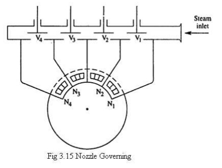
A dynamic arrangement of nozzle control governing
is shown in fig.
In this nozzles are grouped in 3
to 5 or more groups and each group of nozzle is supplied steam controlled by
valves. The arc of admission is limited to 180º or less. The nozzle controlled
governing is restricted to the first stage of the turbine, the nozzle area in
other stages remaining constant. It is suitable for the simple turbine and for
larger units which have an impulse stage followed by an impulse reaction
turbine.
Solved
Problems:
1. A convergent divergent
adiabatic steam nozzle is supplied with steam at 10 bar and 250°c.the discharge
pressure is 1.2 bar.assuming that the nozzle efficiency is 100% and initial
velocity of steam is 50 m/s. find the discharge velocity.
Given Data:-
Initial
pressure(p1)=10bar Initial
Temperature(T1)=250°c
Exit
pressure(p2)=1.2 bar
Nozzle
efficiency(ηnozzle)=100%
Initial
velocity of steam (v1)=50m/s
To Find:-
Discharge
velocity (v2)
Solution:-
From
steam table, For 10 bar, 250°c, h1=2943 KJ/kg s1=6.926
KJ/kgk
From
steam table, For 1.2 bar,
hf2
=439.3 KJ/kg ; hfg2=2244.1
KJ/kg;
sf2=1.3
61 KJ/kg K ; sfg2=5.937
KJ/kgK.
Since
s1=s2,
S1=sf
2+x2sfg2
6.926=1.361+x2(5.937)
X2=0
.9373
We
know that,
h2=hf2+x2hfg2
=
439.3+(0.9373)2244.1
h2
= 2542KJ/Kg
Exit
velocity (V2) = Rt[(2000(2943) 2542) + 502]
=
896.91m/s.
2. Dry
saturated steam at 6.5 bar with negligible velocity expands isentropically in a
convergent divergent nozzle to 1.4 bar and dryness fraction 0.956. De termine
the final velocity of steam from th e nozzle if 13% heat is loss in friction.
Find th e % reduction in the final velocity.
Given data:
Exit
pressure (P2) = 1.4 bar
Dryness
fract ion (X2) = 0.956
Heat
loss = 13%
To Find:
The
percent reduction in final velocity
Solution:
From steam table for initial
pressure P1 = 6.5bar, take values h1 =
h1
= 2758.8KJ/Kg
Similarly,
at 1.4 bar,
hfg2
= 2231.9 KJ/Kg
hf2
= 458.4KJ/Kg
h2
= hf2 + X2 hfg2
=
458.4 + (0.956) 2231.6
h2
= 2592.1 KJ/Kg
Final
velocit y (V2) = Rt (2000(h1-h2) )
V2
= 577.39 m/s
Heat
drop is 13%= 0.13
Nozzle
efficiency (η) = 1- 0.13 = 0.87
Velocity
of s team by considering the nozzle efficiency,
y
(V2) = Rt (2000(h1-h2) ) x η
V2 = 538.55 m/s
= % reductio n in final
velocity = 6.72%
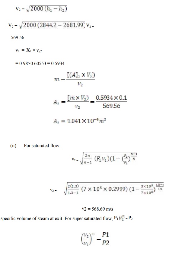
3.A
convergent divergent nozzle
receives steam at
7bar and 200oc and
it expands isentropically into a space of 3bar
neglecting the inlet velocity calculat e the exit area required for a mass flow
of 0.1Kg/sec . when the flow is in equilibrium through all and super saturated
with PV1.3=C.
Given
Data:
Initiall
pressure (P1) = 7bar = 7× 10⁵N/m2
Initiall
temperature (T1) = 200oC
Press
ure (P2) = 3bar = 3× 10⁵N/m2
Mass
flow rate (m) = 0.1Kg/sec
PV1.3
=C
To
Find:
Exit
area
Solution:
From
st eam table for P1 = 7bar and T1 = 200oC V1 =
0.2999
h1
= 2844.2
S1
= 6.886
Similarly
for P2 = 3bar
Vf2
= 0.001074 Vg2 = 0.60553 hf2 =
561.5
hfg2 = 2163.2
Sf2
= 1.672 Sfg2 = 5.319
We know that, S1 = S2 = St
S1
= Sf2 + X2 Sfg2
6.886
= 1.672 + X2 (5.319) X2 =
0.98
Similarly,
h2
= hf2 + X2 hfg2
h2
= 561.5 + 0.98 (2163.2)
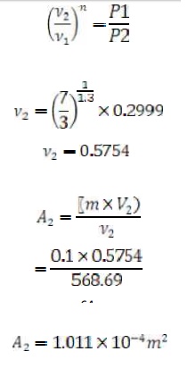
(i)
Flow is in equilibriu m through all:
V2=569.56
ν2 = X2
×
νg2
=
0.98× 0.60553 = 0.5934
TECHNICAL
TERMS
1.Diaphragm - Partitions b etween pressure stages in a
turbine's casing.
2. Radial - flow turbine - st eam flows
outward from the shaft to the casing.
3. Radial clearance - cleara nce at the
tips of the rotor and casing.
4. Axial clearance - the fore -and-aft clearance,
at the sides of the rotor and t he casing.
5. balance piston - Instead of piston,
seal strips are also used to duplicate a piston's counter force.
6. steam rate - The steam rate is the
pounds of steam that must be supplied per kilowatt-hour of generator output at
the steam turbine inlet.
7. extraction turbine
- ste am is
withdrawn from one
or more stages,
at one or
more pressures, for heating, pl
ant process, or feedwater heater needs.
8. Wet steam: The steam w hich contains some
water particles in superposition.
9. Dry steam / dry saturated steam: When
whole mass of steam is converted into steam then it is called as dry steam.
10. Super heated steam: When the dry
steam is further heated at consta nt pressure, the temperature increases the
above saturation temperature. The steam has obtained is called super heated
stea m.
11. Degree of super heat: The difference
between the temperature of saturated steam and saturated temperature is c alled
degree of superheat.
12. Nozzle:It is a duct of varying cross
sectional area in which the velocity increases with the corresponding drop in
pressure.
13. Coefficient of nozzle: It is the
ratio of actual enthalpy drop to isentropic enthalpy drop.
14. Critical pressure ratio: There is only one value of ratio (P2/P1)
which produces maximum discharge fro m
the nozzle . then the ratio is called critica l pressure ratio.
15. Degree of reaction: It is defined as the ratio of isentropic heat drop
in th e moving blade to isentrpic heat
drop in the entire stages of the reaction turbine.
16. Compounding: It is the method of
absorbing the jet velocity in stages when the steam flows over moving blades.
(i)Velocity compounding (ii)Pressure compounding and (iii) Velocity-pressure compounding
17. Enthalpy: It is the combination of
the internal energy and the flow energy.
18. Entropy: It is the function of
quantity of heat with respective to the temperature.
19. Convergent nozzle: The crossectional
area of the duct decreases from inlet to the outlet side then it is called as
convergent nozzle.
20. Divergent nozzle: The crossectional
area of the duct increases from inlet to the outlet then it is called as
divergent nozzle.
Related Topics