Chapter: Mechanical : Design of Transmission Systems : Spur Gears and Parallel Axis Helical Gears
Spur Gears and Parallel Axis Helical Gears
SPUR GEARS AND PARALLEL
AXIS HELICAL GEARS
Gear Terminology
The following terms, which will be mostly used in this chapter, should
be clearly understood at this stage.
1. Pitch circle. It is an imaginary circle which
by pure rolling action, would give the same
motion as the actual gear
2. Pitch circle diameter. It is
the diameter of the pitch circle. The size of the gear is usually specified by the pitch circle
diameter. It is also called as pitch diameter.
3. Pitch point. It is a common point of contact
between two pitch circles.
4. Pitch surface. It is the surface of the
rolling discs which the meshing gears have replaced at the pitch circle.
5. Pressure angle or angle of obliquity. It is
the angle between the common normal to two
gear teeth
at the point of contact and the common tangent at the pitch point. It is
usually denoted by φ. The standard pressure angles are 1 14 /2° and 20°.
6. Addendum. It is the radial distance of a
tooth from the pitch circle to the top of the tooth.
7. Dedendum. It is the radial distance of a
tooth from the pitch circle to the bottom of the tooth.
8. Addendum circle. It is the circle drawn through
the top of the teeth and is concentric with
the pitch circle.
9. Dedendum circle. It is the circle drawn
through the bottom of the teeth. It is also called
root
circle.
Note : Root
circle diameter = Pitch circle diameter × cos φ, where φ is the
pressure angle.
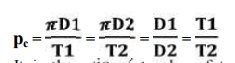
10. Circular pitch. It is the distance
measured on the circumference of the pitch circle from a point of one tooth to the
corresponding point on the next tooth. It is usually denoted by pc.
Mathematically,
Circular
pitch, pc = π D/T
Where, D = Diameter of the pitch circle, and
T = Number of teeth on the wheel.
A little consideration will show that the two gears will mesh together
correctly, if the
two
wheels have the same circular pitch.
Note : If
D1 and D2 are the diameters of the two meshing gears having the teeth T1 and T2
respectively; then for them to mesh correctly,
11.Diametral
pitch. It is the ratio of number of teeth to the pitch circle diameter in
millimetres. It denoted by pd. Mathematically,
Diametral
pitch,
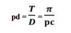
where T
= Number of teeth, and
D
= Pitch circle diameter.
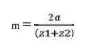
12. Module. It is the ratio of the pitch
circle diameter in millimetres to the number of teeth. It is usually denoted by
m. Mathematically,
Module, m = D / T
Note : The recommended series of
modules in Indian Standard are 1, 1.25, 1.5, 2, 2.5, 3, 4, 5, 6, 8, 10, 12, 16, 20, 25, 32, 40 and
50.
The
modules 1.125, 1.375, 1.75, 2.25, 2.75, 3.5, 4.5,5.5, 7, 9, 11, 14, 18, 22, 28,
36 and 45 are of second choice.
13.
Clearance. It is
the radial distance from the top of the tooth to the bottom of the tooth, in a meshing gear. A circle passing
through the top of the meshing gear is known as clearance circle.
14.
Total
depth. It is the radial distance between the addendum and the dedendum circle
of a gear. It is equal to the sum of
the addendum and dedendum.
15.Working depth. It is radial distance from the
addendum circle to the clearance circle. It
is equal to the sum of the addendum of the two meshing gears.
16.
Tooth
thickness. It is the width of the tooth measured along the pitch circle.
17.Tooth space. It is the width of space between
the two adjacent teeth measured along the
pitch circle.
18. Backlash. It is the difference between
the tooth space and the tooth thickness, as
measured on the pitch circle.
19.
Face of
the tooth. It is surface of the tooth above the pitch surface.
20.
Top land. It is
the surface of the top of the tooth.
21.
Flank of
the tooth. It is the surface of the tooth below the pitch surface.
22.Face width. It is the width of the gear
tooth measured parallel to its axis.
23.
Profile. It is
the curve formed by the face and flank of the tooth.
24.
Fillet
radius. It is the radius that connects the root circle to the profile of the
tooth.
25. Path of contact. It is the path traced by the
point of contact of two teeth from the beginning
to the end of engagement.
26. Length of the path of contact. It is
the length of the common normal cut-off by the addendum circles of the wheel and pinion.
27.Arc of contact. It is the path traced by a
point on the pitch circle from the beginning to the end of engagement of a given pair of teeth. The arc of contact
consists of two parts, i.e.
(a) Arc of approach. It is the portion of
the path of contact from the beginning of the engagement
to the
pitch point.
(b) Arc of recess. It is the portion of the
path of contact from the pitch point to the end of the engagement of a pair of
teeth.
Note: The ratio of the length of arc
of contact to the circular pitch is known as contact ratio i.e. number of pairs of teeth in contact.
Speed ratios and number of
teeth
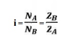
It is the
ratio of speed of driving gear to the speed of the driven gear.
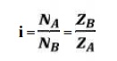
where, NA and NB
= speed of the driver and driven respectively, and ZA and ZB
= Number of teeth on driver and driven respectively.
Force analysis
1. Tangential component:
The tangential component Ft is a useful component. Because it
transmit power. Using the value of Ft , the magnitude of torque and
transmitted power can be determined.
Transmitted power Wt = Ft
2. Radial component:
The radial component Fr is a separating force which is always
directed towards the centre of the gear. Fr does not really a useful
component. It is also called as transverse force or bending force.
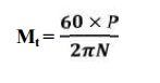
Let P =
Power transmitted (W)
Mt = Torque transmitted (N-m)
N1
and N2 = Speed of pinion and
gear respectively
d1
and d2 =
Pitch circle diameters of pinion and gear respectively
ϕ = Pressure angle.
The
torque transmitted by gear
DESIGN PROCEDURE FOR SPUR GEAR:
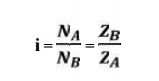
1.
Calculation
of gear ratio (i):
where, NA and NB
= speed of the driver and driven respectively, and ZA and ZB
= Number of teeth on driver and driven respectively.
2. Selection
of material
Consulting Table 5.3, knowing the gear ratio i,
choose the suitable material.
3. If not
given, assume gear life (say 20000 hrs)
4.
Calculation
of initial design torque:
[Mt] = Mt . K. Kd
where, [Mt] = transmission torque
K = Load
factor, Table 5.11
Kd =
Dynamic load factor, Table 5.12
Assume K. Kd = 1.3 ( if not given)
5.
Calculation
of Eeq, [ϭb] and [ϭc]:
ü From
table 5.20 Calculate Eeq
ü From
table 5.16 Calculate Design bending stress
[ϭb]
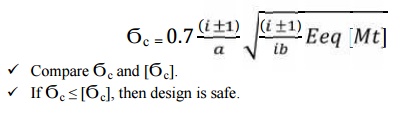
ü Calculate
Design contact stress [ϭc] by
[ϭc] = CB . HB. Kcl (or)
[ϭc] = CR . HRC. Kcl
where, CB
CR = Coefficient of surface hardness from table 5.18
HB HRC = Hardness number
6.
Calculation
if centre distance (a):
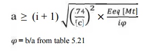
6.
Select
number of teeth on gear and pinion:
Ø On
pinion,Z1 = Assume 18
Ø On gear, Z2 = i X Z1
8. Calculation of module:
Choose standard module from table 5.8
9. Revision
of centre distance(m)
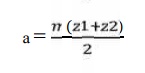
10. Calculate
b, d1, v and ѱp :
Calculate
face width, b = ѱ. a
Calculate
pitch dia, d = m.z1
Calculate pitch
line velocity, v = (πd1N1)/60
Calculate
value of ѱp = b/d1
11.
Selection of quality of gear:
Knowing the pitch line velocity and consulting
table 5.22, select a suitable quality
of gear.
12.
Revision of design torque [Mt]: Revise K:
Using the calculated value of ѱp revise
the K value by using table 5.11
Revise Kd:
Using the selected quality if gear and pitch line
velocity, revise the Kd
value
[Mt] = Mt . K. Kd
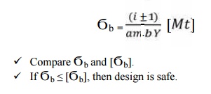
13. Check
for bending:
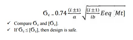
14. Check
for wear strength:
Calculate induced contact stress,
15. If the design is not satisfactory (ϭb
> [ϭb] and / or ϭc > [ϭc] ), then
increase the module of face width value of the gear material.
16. Check
for gear:
a.
Check for
bending:
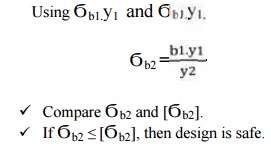
If Ϭb2 ≤ [Ϭb2], then design
is safe.
b. Check
for wear strength:
Calculate induced contact stress will be same for
pinion and gear,
So,
Ϭc2 = Ϭc
ü Compare Ϭc
and [Ϭc]
ü If Ϭc
≤ [Ϭc], then design is safe
DESIGN
PROCEDURE FOR HELICAL GEAR:
1. Calculation of gear ratio (i):
where, NA and NB
= speed of the driver and driven respectively, and ZA and ZB
= Number of teeth on driver and driven respectively.
2. Selection
of material
Consulting Table 5.3, knowing the gear ratio i,
choose the suitable material.
3. If not
given, assume gear life (say 20000 hrs)
4.
Calculation
of initial design torque:
[Mt] = Mt . K. Kd
where, [Mt] = transmission torque
K = Load
factor, Table 5.11
Kd =
Dynamic load factor, Table 5.12
Assume K. Kd = 1.3 ( if not given)
5.
Calculation
of Eeq, [ϭb] and [ϭc]:
ü From
table 5.20 Calculate Eeq
ü From
table 5.16 Calculate Design bending stress
[ϭb]
ü Calculate
Design contact stress [ϭc] by
[ϭc] = CB . HB. Kcl (or)
[ϭc] = CR . HRC. Kcl
CB CR = Coefficient of
surface hardness from table 5.18
HB HRC = Hardness number
6.
Calculation
if centre distance (a):
7.Select number of teeth on gear and pinion:
Ø On
pinion,Z1 = Assume ≥ 17
Ø On gear, Z2 = i X Z1
8. Calculation
of module:
Choose standard module from table 5.8
9. Revision
of centre distance (m):
10. Calculate
b, d1, v and ѱp :
Calculate
face width, b = ѱ. a
Calculate
pitch dia, d = (mn.z1)/ cos β
Calculate
pitch line velocity, v = (πd1N1)/60
Calculate
value of ѱp = b/d1
11. Selection
of quality of gear:
Knowing the pitch line velocity and acosulting
table 5.22, select a suitable quality
of gear.
12.
Revision of design torque [Mt]: Revise K:
Using the calculated value of ѱp revise
the K value by using table 5.11
Revise Kd:
Using the selected quality if gear and pitch line
velocity, revise the Kd
value
[Mt] = Mt . K. Kd
13. Check
for bending:
Compare Ϭb
and [Ϭb].
If Ϭb ≤ [Ϭb], then design is
safe.
14. Check
for wear strength:
Calculate induced contact stress,
If Ϭc ≤ [Ϭc], then design is
safe.
15. If the design is not satisfactory (ϭb > [ϭb]
and / or ϭc > [ϭc] ), then increase the module of face width value of the gear material.
16. Check
for gear:
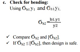
ü Compare Ϭb2
and [Ϭb2].
ü If Ϭb2
≤ [Ϭb2], then design is safe.
d. Check for wear strength:
Calculate induced contact stress will be same for
pinion and gear,
So,
Ϭc2 = Ϭc
ü Compare Ϭc
and [Ϭc]
ü If Ϭc
≤ [Ϭc], then design is safe
SOLVED PROBLEMS
1.
The
following particulars of a single reduction spur gear are given : Gear ratio =
10 : 1; Distance between centres = 660 mm approximately; Pinion transmits 500
kW at 1800 r.p.m.; Involute teeth of standard proportions (addendum = m) with
pressure angle of 22.5°; Permissible normal pressure between teeth = 175 N per
mm of width. Find :
1. The nearest standard module if no interference is
to occur;
2. The number of teeth on each wheel;
3. The necessary width of the pinion; and
4.
The load
on the bearings of the wheels due to power transmitted.
Solution : Given :
G = TG / TP = DG / DP = 10 ;
L = 660 mm ;
P = 500 kW = 500 × 103 W;
NP = 1800 r.p.m. ; φ = 22.5° ;
WN = 175 N/mm width
1. Nearest standard module if no interference is to
occur
Let m = Required module,
TP = Number of teeth on the pinion,
TG = Number of teeth on the gear,
DP = Pitch circle diameter of the pinion, and
DG = Pitch circle diameter of the gear.
We know that minimum number of teeth on the pinion
in order to avoid interference,

we
already know that,
L = (DG / 2) + (Dp
/ 2) = 5.5 Dp
We also
know that
∴ DP
= m . TP
=
DP / TP = 120 / 14
m
= 8.6 mm
Since
the nearest standard value of the module is 8 mm, therefore we shall take
m = 8 mm
Ans.
2. Number of teeth on each wheel
We know that number of teeth on the pinion,
TP = DP / m = 120 / 8 = 15 Ans.
and number of teeth on the gear,
TG = G × TP = 10 × 15 = 150 Ans.
3. Necessary width of the pinion
We know that the torque acting on the pinion,
T = 60P/(2πN)
= 2652
N-m
Tangential load, WT = T/(DP/2)
= 2652 / (20.12 / 2)
T = 44200
N
WN = Wt/cosϕ
= 44200 / cos 22.5
W = 47
840 N
Since the
normal pressure between teeth is 175 N per mm of width, therefore necessary
width of
the
pinion,
b = 47840 / 175
=273.4 mm
Ans.
4. Load on the bearings of the wheels
We know
that the radial load on the bearings due to the power transmitted,
WR = WN . sin φ
= 47 840 ×
sin 22.5°
= 18 308 N
= 18.308 kN An
2.
A bronze
spur pinion rotating at 600 r.p.m. drives a cast iron spur gear at a
transmission ratio of 4 : 1. The allowable static stresses for the bronze
pinion and cast iron gear are 84 MPa and 105 MPa respectively. The pinion has
16 standard 20° full depth involute teeth of module 8 mm. The face width of
both the gears is 90 mm. Find the power that can be transmitted from the
standpoint of strength.
Solution.
Given :
NP = 600 r.p.m. ;
V.R. = TG / TP = 4 ;
σOP = 84 MPa = 84 N / mm2 ; σOG = 105 MPa = 105 N/mm2 ;
TP = 16 ;
m = 8 mm ;
b = 90 mm
We know
that pitch circle diameter of the pinion,
DP
= m.TP = 8 × 16 = 128 mm = 0.128 m
velocity,
∴ Pitch line
v
= πDN/60
=
4.02 m/s
We know
that for 20° full depth involute teeth, tooth form factor for the pinion,
yP = 0.154 – (.912/ Tp)
= 0.097
and tooth form factor for the gear
yG = 0.154 – (.912/ TG)
= 0.14
σOP × yP = 84 × 0.097 = 8.148
and σOG × yG = 105 × 0.14 = 14.7
Since
(σOP × yP) is less than ( σOG × yG), therefore the pinion is weaker. Now using
the Lewis equation for the pinion, we have tangential load on the tooth (or
beam strength of the tooth),
WT = σwP.b.π m.yP
= (σOP × Cv) b. π m.yP (Q σWP = σOP.Cv)
= 84 × 0.427 × 90 ×
π × 8 × 0.097 = 7870 N
∴ Power that can be transmitted = WT × v
= 7870 ×
4.02
= 31 640 W
= 31.64 kW Ans.
3.
A pair of
helical gears are to transmit 15 kW. The teeth are 20° stub in diametral plane
and have a helix angle of 45°. The pinion runs at 10 000 r.p.m. and has 80 mm
pitch diameter. The gear has 320 mm pitch diameter. If the gears are made of cast
steel having allowable static strength of 100 MPa; determine a suitable module
and face
width
from static strength considerations and check the gears for wear, given σes =
618 MPa.
Solution.
Given :
P = 15 kW = 15 × 103 W;
φ = 20° ; α = 45° ;
NP = 10 000 r.p.m. ;
DP = 80 mm = 0.08 m ;
DG = 320 mm = 0.32 m ;
σOP = σOG = 100 MPa = 100 N/mm2 ; σes = 618 MPa =
618 N/mm2
Module
and face width
Let m = Module in mm, and b =
Face width in mm.
Since both the pinion and gear are made of the same material (i.e. cast
steel), therefore the pinion is weaker. Thus the design will be based upon the
pinion.
We know
that the torque transmitted by the pinion,
T = (60P) / (2πN)
= 14.32 N-m.
Tangential tooth load on the pinion,
WT
= T / (Dp/2)
We know
that number of teeth on the pinion,
TP = DP / m = 80 / m
and formative or equivalent
number of teeth for the pinion, TE = TP / cos3
α
= 226.4 / m
∴ peripheral velocity,
v = (π Dp
Np) / 60
= 42 m/s
Velocity
factor, Cv =
0.104
Since the
maximum face width (b) for helical gears may be taken as 12.5 m to 20 m, where
m is the module, therefore let us take
b = 12.5 m
We know
that the tangential tooth load (WT),
358 = (σOP . Cv) b.π m.y'P
= (100 ×
0.104) 12.5 m × π m (0.175 – 0.0037 m)
= 409 m2
(0.175 – 0.0037 m)
= 72 m2 –
1.5 m3
Solving this expression by hit
and trial method, we find that m = 2.3 say 2.5
mm Ans.
and face
width, b =
12.5 m = 12.5 × 2.5 = 31.25 say 32 mm
Ans.
Checking the gears for wear
We know
that velocity ratio,
V.R. = DG / DP
= 320 / 80
= 4
We know
that the maximum or limiting load for wear,
Ww = (D bQK) / cos2a
= 5554 N
A helical cast steel gear with 30° helix angle has
to transmit 35 kW at 1500 r.p.m. If the gear has 24 teeth, determine the
necessary module, pitch diameter and face width for 20° full depth teeth. The
static stress for cast steel may be taken as 56 MPa. The width of face may be
taken as 3 times the normal pitch. What would be the end thrust on the gear?
The tooth factor for 20° full depth involute gear may be taken as 0.154 –
0.912/T where TE represents the equivalent number of teeth.
Solution.
Given :
α = 30° ;
P = 35 kW = 35 × 103 W ;
N = 1500 r.p.m. ;
TG = 24 ;
φ = 20° ;
σo = 56 MPa = 56 N/mm2 ; b = 3 × Normal pitch = 3
pN
Module
Let m = Module in mm, and
DG = Pitch circle diameter of the gear in mm. We
know that torque transmitted by the gear,
T = (60P) / (2πN)
= 223x103 N-mm.
Formative or equivalent number of teeth,
TE = TP / cos3 α
= 37.
∴ Tooth factor, y' = 0.154 – 0.912/T
= 0.129
Tangential tooth load on the pinion,
WT
= T / (Dp/2)
∴ = 18600 / m peripheral
velocity,
v = (π Dp Np) / 60
= 1.885m
m/s
Velocity factor, Cv = 0.75 / (0.75 + v )
= 0.75 /
(0.75 + 1.885m )
We know
that tangential tooth load,
WT = (σo
× Cv) b. π m.y' = (σo × Cv) 3pN × π m ×
y'
= (σo × Cv) 3 × pc cos α × π m × y'
α)
= (σo ×
Cv) 3 π m cos α × π m × y'
... (Q b = 3 pN)
... (Q pN = pc cos
... (Q pc = π m)
Solving
this equation by hit and trial method, we find that
m = 5.5
say 6 mm Ans
Pitch diameter of the gear
We know
that the pitch diameter of the gear,
DG = m × TG = 6 × 24 = 144 mm Ans.
Face width
It is
given that the face width,
b = 3 pN = 3 pc cos α = 3 × π m
cos α
= 3 × π × 6
cos 30°
= 48.98 say
50 mm Ans.
End thrust on the gear
We know
that end thrust or axial load on the gear,
WA = Wr tan a
= 1790 N
Related Topics