Chapter: Power System Analysis : Introduction
Solved problems and Examples on Per Unit Analysis
EXAMPLES ON RULE OF INSPECTION:
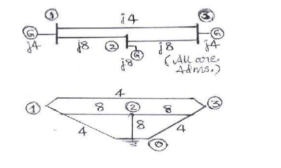
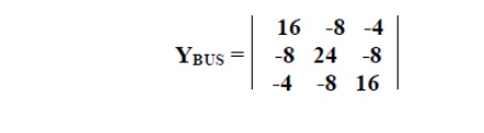
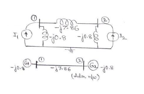
Problem #1: Obtain the bus admittance matrix for the admittance network shown aside by the rule of inspection
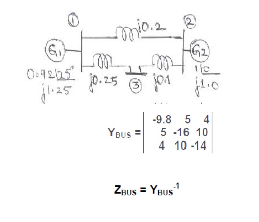
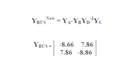
Problem #2: Obtain YBUS and ZBUS matrices for the impedance network shown aside by the rule of inspection. Also, determine YBUS for the reduced network after eliminating the eligible unwanted node. Draw the resulting reduced system diagram.
EXAMPLES ON PER UNIT ANALYSIS:
Problem #0:
Two generators rated 10 MVA, 13.2 KV and 15 MVA, 13.2 KV are connected in parallel to a bus bar. They feed supply to 2 motors of inputs 8 MVA and 12 MVA respectively.
The operating voltage of motors is 12.5 KV. Assuming the base quantities as 50 MVA, 13.8 KV, draw the per unit reactance diagram. The percentage reactance for generators is 15% and that for motors is 20%.
Solution:
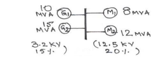
The one line diagram with the data is obtained as shown in figure
Problem #1:
Two
generators rated 10 MVA, 13.2 KV and 15 MVA, 13.2 KV are connected in parallel
to a bus bar. They feed supply to 2 motors of inputs 8 MVA and 12 MVA
respectively. The operating voltage of motors is 12.5 KV. Assuming the base
quantities as 50 MVA, 13.8 KV, draw the per unit reactance diagram. The
percentage reactance for generators is 15% and that for motors is 20%.
Solution:
The one
line diagram with the data is obtained as shown in figure P1(a).
Selection of base quantities: 50 MVA,
13.8 KV (Given)
Calculation of pu values:
XG1
= j 0.15 (50/10) (13.2/13.8)2 = j 0.6862 pu.
XG2
= j 0.15 (50/15) (13.2/13.8)2 = j 0.4574 pu.
Xm1
= j 0.2 (50/8) (12.5/13.8)2 = j 1.0256 pu.
Xm2
= j 0.2 (50/12) (12.5/13.8)2 = j 0.6837 pu.
Eg1
= Eg2 = (13.2/13.8) = 0.9565 ∠00
pu
Em1
= Em2 = (12.5/13.8) = 0.9058 ∠00
pu
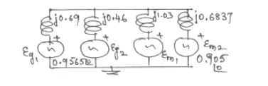
Thus the
pu reactance diagram can be drawn as shown in figure P1(b).
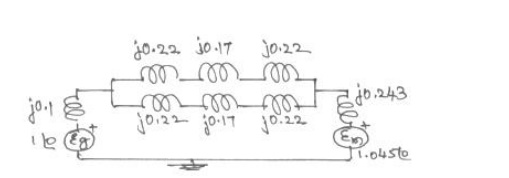
Problem #2:
Draw the
per unit reactance diagram for the system shown in figure below. Choose a base
of 11 KV, 100 MVA in the generator circuit.
Solution:
The one
line diagram with the data is considered as shown in figure.
Selection of base quantities:
100 MVA, 11 KV in the generator circuit(Given);
the voltage bases in other sections are: 11 (115/11.5) = 110 KV in the transmission line circuit and 110 (6.6/11.5) = 6.31 KV in the motor circuit.
Calculation of pu values:
Calculation
of pu values:
XG
= j 0.1 pu, Xm = j 0.2 (100/90) (6.6/6.31)2 = j 0.243 pu.
Xt1
=Xt2 = j 0.1 (100/50) (11.5/11)2 = j 0.2185 pu.
Xt3
=Xt4 = j 0.1 (100/50) (6.6/6.31)2 = j 0.219 pu.
Xlines
= j 20 (100/1102) = j 0.1652 pu.
Eg
= 1.0∠00 pu, Em = (6.6/6.31) =
1.045∠00 pu
Thus the
pu reactance diagram can be drawn as shown in figure P2(b).
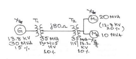
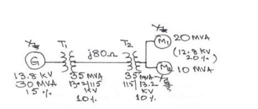
Problem #3:
A 30 MVA,
13.8 KV, 3-phase generator has a sub transient reactance of 15%. The generator
supplies 2 motors through a step-up transformer - transmission line – step-down
transformer arrangement. The motors have rated inputs of 20 MVA and 10 MVA at
12.8 KV with 20% sub transient reactance each. The 3-phase
transformers
are rated at 35 MVA, 13.2 KV -∆ /115
KV-Y with 10 % leakage reactance. The line reactance is 80 ohms. Draw the
equivalent per unit reactance diagram by selecting the generator ratings as
base values in the generator circuit.
Solution:
The one
line diagram with the data is obtained as shown in figure P3(a).
Selection of base quantities:
30 MVA, 13.8 KV in the generator
circuit(Given); The voltage bases in
other sections are:
13.8(115/13.2) = 120.23 KV in the transmission line circuit and
120.23(13.26/115)
= 13.8 KV in the motor circuit.
Calculation of pu values:
XG
= j 0.15 pu.
Xm1
= j 0.2 (30/20) (12.8/13.8)2 = j 0.516 pu.
Xm2
= j 0.2 (30/10) (12.8/13.8)2 = j 0.2581 pu.
Xt1
=Xt2 = j 0.1 (30/35) (13.2/13.8)2 = j 0.0784 pu.
Xline
= j 80 (30/120.232) = j 0.17 pu.
Eg
= 1.0∠00
pu; Em1 = Em2 =
(6.6/6.31) = 0.93∠00 pu
Thus the
pu reactance diagram can be drawn as shown in figure P3(b).
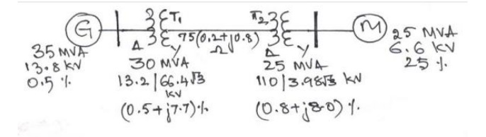
Problem #4:
A 33 MVA, 13.8 KV, 3-phase generator
has a sub transient reactance of 0.5%. The generator supplies a motor through a
step- up transformer - transmission line – step-down transformer arrangement.
The motor has rated input of 25 MVA at 6.6 KV with 25% sub transient reactance.
Draw the equivalent per unit impedance diagram by selecting 25 MVA (3φ), 6.6 KV (LL) as base values in the motor circuit, given
the transformer and transmission line data as under:
Step up transformer bank: three single phase units, connected ∆–Y, each rated 10 MVA, 13.2/6.6 KV
with 7.7 % leakage reactance and 0.5
% leakage resistance;
Transmission line: 75 KM long with a positive sequence reactance of 0.8 ohm/ KM
and a resistance of 0.2 ohm/ KM; and
Step down transformer bank: three single phase units, connected ∆–Y, each rated 8.33 MVA, 110/3.98 KV with 8% leakage reactance and 0.8 % leakage
resistance;
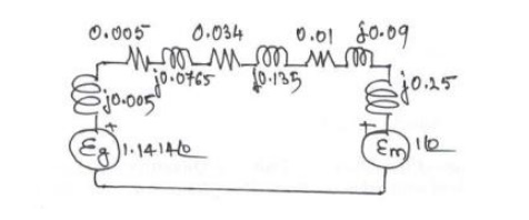
Solution:
The one line diagram with the data
is obtained as shown in figure P4(a).
3-phase
ratings of transformers:
T1:
3(10) = 30 MVA, 13.2/ 66.4√3 KV = 13.2/ 115 KV, X = 0.077, R
= 0.005 pu.
T2:
3(8.33) = 25 MVA, 110/ 3.98√3 KV = 110/ 6.8936 KV, X = 0.08,
R = 0.008 pu.
Selection of base quantities:
25 MVA, 6.6 KV in the motor circuit (Given);
the voltage bases in other sections are: 6.6 (110/6.8936) = 105.316 KV in the transmission line circuit and 105.316 (13.2/115)
= 12.09 KV in the generator circuit.
Calculation of pu values:
Xm
= j 0.25 pu; Em = 1.0∠00
pu.
XG
= j 0.005 (25/33) (13.8/12.09)2 = j 0.005 pu; Eg =
13.8/12.09 = 1.414∠00 pu.
Zt1
= 0.005 + j 0.077 (25/30) (13.2/12.09)2 = 0.005 + j 0.0765 pu. (ref.
to LV side)
Zt2
= 0.008 + j 0.08 (25/25) (110/105.316)2 = 0.0087 + j 0.0873 pu.
(ref. to HV side)
Zline
= 75 (0.2+j 0.8) (25/ 105.3162) = 0.0338 + j 0.1351 pu.
Problems
1. Determine
the reactances of the three generators rated as follows on a common base of 200
MVA, 35 KV: Generator 1: 100 MVA, 33
KV, sub transient reactance of 10%; Generator 2: 150 MVA, 32 KV, sub transient
reactance of 8% and Generator 3: 110 MVA, 30 KV, sub transient reactance of
12%.
[Answers:
XG1 = j 0.1778, Xg2 = j 0.089, Xg3 = j
0.16 all in per unit]
2. A 100 MVA, 33 KV, 3-phase generator has a sub transient reactance of 15%. The generator supplies 3 motors through a step-up transformer - transmission line – step- down transformer arrangement. The motors have rated inputs of 30 MVA, 20 MVA and 50 MVA, at 30 KV with 20% sub transient reactance each. The 3 -phase transformers are rated at 100 MVA, 32 KV-∆ /110 KV-Y with 8 % leakage reactance. The line has a reactance of 50 ohms. By selecting the generator ratings as base values in the generator circuit, determine the base values in all the other parts of the system. Hence evaluate the corresponding pu values and draw the equivalent per unit reactance diagram.
[Answers: X G = j 0.15, Xm1
= j 0.551, Xm2 = j 0.826, Xm3 = j 0.331, Eg1=1.0
∠00,
Em1 = Em2 = Em3 = 0.91∠00,
Xt1 = Xt2 = j 0.0775 and Xline = j 0.39 all in
per unit]
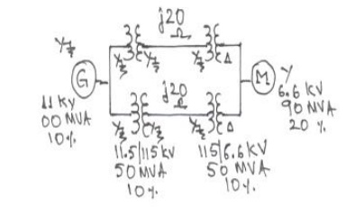
3. A 80 MVA,
10 KV, 3-phase generator has a sub transient reactance of 10%. The generator
supplies a motor through a step -up
transformer - transmission line – step-down transformer arrangement. The motor
has rated input of 95 MVA, 6.3 KV with 15% sub transient reactance. The step-up
3-phase transformer is rated at 90 MVA, 11 KV-Y /110 KV-Y with 10% leakage
reactance. The 3-phase step-down transformer consists of three single phase Y -∆ connected transformers, each
rated at 33.33 MVA, 68/6.6 KV with 10% leakage reactance. The line has a
reactance of 20 ohms. By selecting the 11 KV, 100 MVA as base values in the
generator circuit, determine the base values in all the other parts of the system.
Hence evaluate the corresponding pu values and draw the equivalent per unit
reactance diagram.
[Answers: XG = j 1.103, Xm
= j 0.165, Eg1=0.91∠00, Em=
1.022∠00,
Xt1 = j 0.11, Xt2 = j 0.114 and Xline = j 0.17
all in per unit]
4. For the
three-phase system shown below, draw an impedance diagram expressing all
impedances in per unit on a common
base of 20 MVA, 2600 V on the HV side of the transformer. Using this impedance
diagram, find the HV and LV currents.
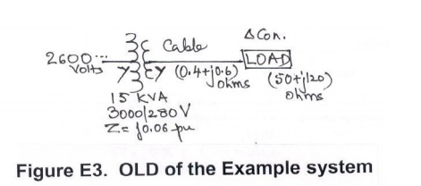
[Answers: Sb = 20 MVA; Vb=2.6 KV
(HV) and 0.2427 KV (LV); Vt=1.0∠00,
Xt = j 0.107, Zcable = 0.136 +j 0.204 and Zload
= 5.66 + j 2.26, I = 0.158 all in per unit, I (hv)= 0.7 A and I (lv) = 7.5 A]
Related Topics