Chapter: Power System Analysis : Introduction
Formation of Y BUS & Z BUS
FORMATION OF Y BUS & Z BUS
The performance equations of a given power system can be considered in three different frames of reference as discussed below:
Frames of Reference:
Bus Frame of Reference: There are b independent equations (b = no. of buses) relating the bus vectors of currents and voltages through the bus impedance matrix and bus admittance matrix:
EBUS = ZBUS IBUS
IBUS = YBUS EBUS
Bus Frame of Reference: There are b independent equations (b = no. of buses) relating the bus vectors of currents and voltages through the bus impedance matrix and bus admittance matrix:
EBUS = ZBUS IBUS
IBUS = YBUS EBUS
Branch Frame of Reference: There are b independent equations (b = no. of branches of a selected Tree sub-graph of the system Graph) relating the branch vectors of currents and voltages through the branch impedance matrix and branch admittance matrix:
EBR = ZBR IBR
IBR = YBR EBR
Loop Frame of Reference: There are b independent equations (b = no. of branches of a selected Tree sub-graph of the system Graph) relating the branch vectors of currents and voltages through the branch impedance matrix and branch admittance matrix:
ELOOP = ZLOOP ILOOP
ILOOP = YLOOP ELOOP
Of the various network matrices refered above, the bus admittance matrix (YBUS ) and the bus impedance matrix (ZBUS ) are determined for a given power system by the rule of inspection as explained next.
Rule of Inspection
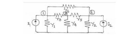
Consider the 3-node admittance network as shown in figure5. Using the basic branch relation:
I = (YV), for all the elemental currents and applying Kirchhoff’s Current Law principle at the nodal points, we get the relations as under:
At node 1: I1 =Y1V1 + Y3 (V1-V3) + Y6 (V1 – V2)
At node 2: I2 =Y2V2 + Y5 (V2-V3) + Y6 (V2 – V1)
At node 3: 0 = Y3 (V3-V1) + Y4V3 + Y5 (V3 – V2)
These are the performance equations of the given network in admittance form and they can be represented in matrix form as:
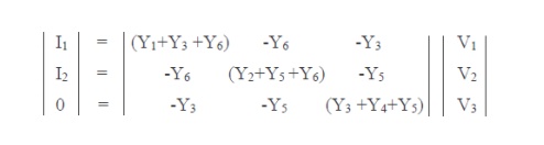
In other words, the relation of equation (9) can be represented in the form IBUS = YBUS EBUS
Where, YBUS is the bus admittance matrix, IBUS & EBUS are the bus current and bus voltage vectors respectively.
By observing the elements of the bus admittance matrix, YBUS of equation (9), it is observed that the matrix elements can as well be obtained by a simple inspection of the given system diagram:
Diagonal elements: A diagonal element (Yii) of the bus admittance matrix, YBUS, is equal to the sum total of the admittance values of all the elements incident at the bus/node i,
Off Diagonal elements: An off-diagonal element (Yij) of the bus admittance matrix, YBUS, is equal to the negative of the admittance value of the connecting element present between the buses I and j, if any.
This is the principle of the rule of inspection. Thus the algorithmic equations for the rule of inspection are obtained as:
Yii = yij (j = 1,2,…….n)
Yij = - yij (j = 1,2,…….n)
For i = 1,2,….n, n = no. of buses of the given system, yij is the admittance of element connected between buses i and j and yii is the admittance of element connected between bus i and ground (reference bus).
Bus impedance matrix
In cases where, the bus impedance matrix is also required, then it cannot be formed by direct inspection of the given system diagram. However, the bus admittance matrix determined by the rule of inspection following the steps explained above, can be inverted to obtain the bus impedance matrix, since the two matrices are inter-invertible.
Note: It is to be noted that the rule of inspection can be applied only to those power systems that do not have any mutually coupled elements.
EXAMPLES ON RULE OF INSPECTION:
Problem #1: Obtain the bus admittance matrix for the admittance network shown aside by the rule of inspection
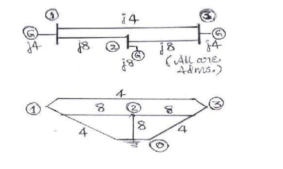
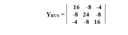
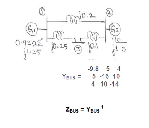
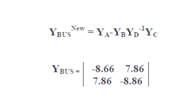
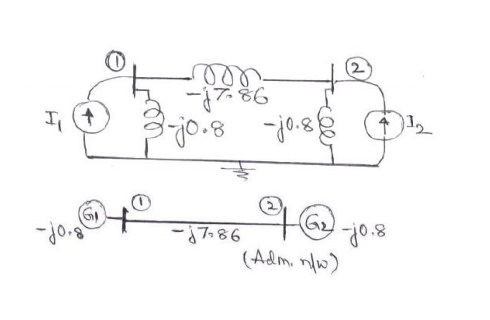
Problem #2: Obtain YBUS and ZBUS matrices for the impedance network shown aside by the rule of inspection. Also, determine YBUS for the reduced network after eliminating the eligible unwanted node. Draw the resulting reduced system diagram.
EXAMPLES ON PER UNIT ANALYSIS:
Problem #1:
Two generators rated 10 MVA, 13.2 KV and 15 MVA, 13.2 KV are connected in parallel to a bus bar. They feed supply to 2 motors of inputs 8 MVA and 12 MVA respectively.
The operating voltage of motors is 12.5 KV. Assuming the base quantities as 50 MVA, 13.8 KV, draw the per unit reactance diagram. The percentage reactance for generators is 15% and that for motors is 20%.
Solution:
The one line diagram with the data is obtained as shown in figure
Related Topics