Chapter: Power System Analysis : Introduction
Modeling of Components For Load Flow Analysis
MODELING OF COMPONENTS FOR LOAD FLOW ANALYSIS
Generator models Generators:
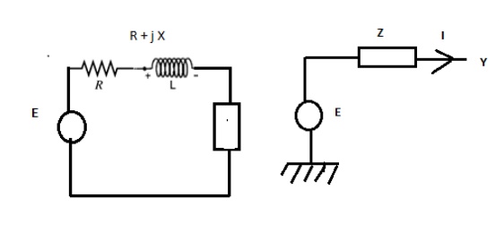
The thevenins equivalent circuit of the generator i.e. The voltage source in series with the thevenins equivalent impedance. Z = R + jX
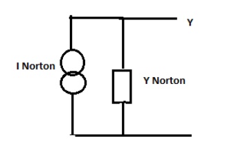
The Norton form equivalent circuit of the generator i.e. The current source in parallel with the admittance
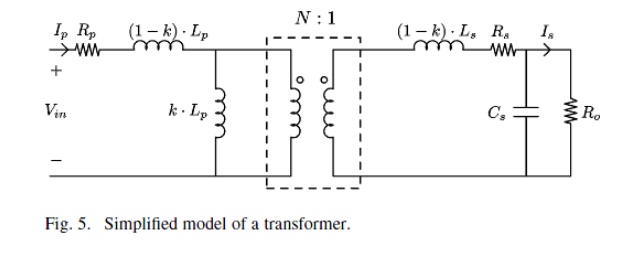
Transformer model
Transmission system model
Transmission Line
Transmission line are modelled as
(i). Short line model
(ii). Medium line model
(iii). Long line model
(i). Short line model : Resistance & inductance are assumed to be lumped
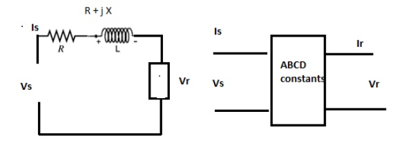
Medium line model (lines between 80 to 250km)
Resistance &inductance are assumed to be lumped &the total shunt admittance is divided in to two equal parts & placed at the receiving and sending ends.
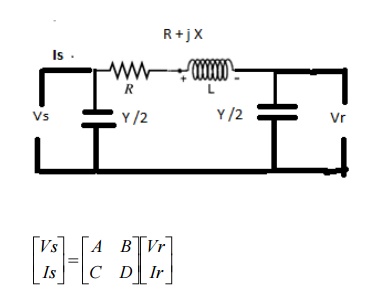
X = Lω
A = 1+ZY/2
B=Z
C=Y(1+ZY/4)
D=1+ZY/4
Long line model (lines above 250)
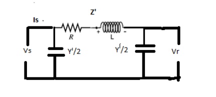
Z’=Z sinhγL / γ L

Shunt Elements:
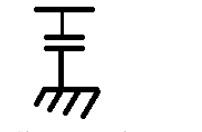
The shunt capacitor is connected to bus i. If S is MVAR rating of shunt capacitor. So is base MVA admittance P.u. Y P.u. = 0+jS/S0
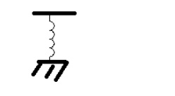
Shunt reactors is connected io bus i. If S is MVAR rating of shunt capacitor. So is base MVA admittance P.u. Y P.u. = 0-jS/S0
Load representation
Load:
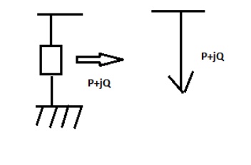
Load is represented by a constant power representation. Both MW (P) & MVAR (Q) – constant
Related Topics