Chapter: Mechanical : Design of Machine Elements : Design of Temporary and Permanent Joints
Solved Problems: Design of Temporary and Permanent Joints
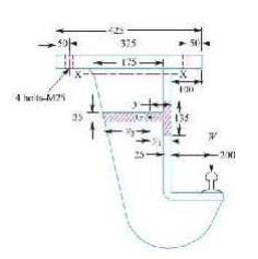
A bracket,
as shown in Figure, supports a load of 30 kN. Determine the size of bolts, if
the maximum allowable tensile stress in the bolt material is 60 MPa. The
distances are : L1 = 80 mm, L2 = 250 mm, and L = 500 mm.
Solution.

Given :
W = 30 kN
σt = 60
MPa = 60 N/mm2 L1 = 80 mm
L2 = 250
mm L = 500 mm
We know that the direct tensile load carried by
each bolt, Wt1 = (W / n)
=30 / 4
=7.5 kN
Load in a
bolt per unit distance,
= WL / 2[(L1)2 + (L2)2]
=30 x 500 / 2[802 + 2502]
=0.109 kN/mm
Since the heavily loaded bolt is at a distance of
L2 mm from the tilting edge, therefore load on the heavily loaded bolt,
Wt2 = w.L2
=0.109 × 250
=27.25 kN
Maximum
tensile load on the heavily loaded bolt,
Wt = Wt1 + Wt2
=7.5 + 27.25
34.75 kN = 34750 N
Let dc =
Core diameter of the bolts.
We know
that the maximum tensile load on the bolt (Wt), 34750 = (π / 4) × (dc)2
σt
(dc)2 = 34750 / 47 = 740
dc = 27.2 mm
From
Table 11.1 (coarse series), we find that the standard core diameter of the bolt
is 28.706
mm and the
corresponding size of the bolt is M 33.
Design a
sleeve and cotter joint to resist a tensile load of 60 kN. All parts of the
joint are made of the same material with the following allowable stresses : σt = 60 MPa ; τ= 70MPa
and σc = 125 MPa
Solution.
Given :
σc = 125 MPa = 125 N/mm2
1.
Diameter of the rods
Let d =
Diameter of the rods. Considering the failure of the rods in tension.
We know
that load (P),
60 × 103
= π
x d2 x σt
4
d2 = 60 × 103/ 47.13 = 1273
= 35.7 say 36 mm
Diameter
of enlarged end of rod and thickness of cotter
Let d2 = Diameter of enlarged end of rod, and
t =
Thickness of cotter. It may be taken as d2 / 4.
Considering
the failure of the rod in tension across the weakest section (i.e. slot). We
know that
load (P),
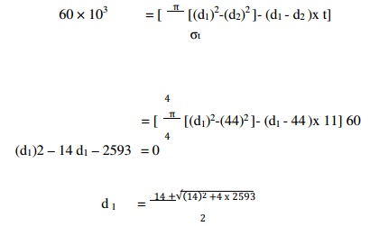
60 × 103
= [ π (d2)2 - d2 x t]
σt
4
= [ π (d2)2 - d2 x (d2/4)] 60
4
= 32.13
(d2)2
(d2)2 = 60 × 103 / 32.13 = 1867
d2 = 43.2 say
44 mm
Thickness
of cotter,
= (d2/4) = 44/4
=11
mm
Let us
now check the induced crushing stress in the rod or cotter. We know that load
(P), 60 × 103 = d2 × t ×σc
=44 × 11 × σc
=484 σc
σc = 60 × 103 / 484
=
124 N/mm2
Since the
induced crushing stress is less than the given value of 125 N/mm2, therefore
the dimensions d2 and t are within safe limits.
3. Outside
diameter of sleeve
Let d1 =
Outside diameter of sleeve.
Considering
the failure of sleeve in tension across the slot.
We know
that load (P)

=
58.4 say 60 mm.
4. Width
of cotter
Let b =
Width of cotter.
Considering the failure of cotter in shear. Since
the cotter is in double shear, therefore load (P), 60 × 103 = 2 b × t × τ
=2 × b × 11 × 70
=1540 b
= 60 × 103 / 1540
=
38.96 say 40 mm
Distance
of the rod from the beginning to the cotter hole (inside the sleeve end)
Let a =
Required distance.
Considering
the failure of the rod end in shear. Since the rod end is in double shear,
therefore load (P),
60 103
= 2 a × d2 × τ
=2 a × 44 × 70
=6160 a
= 60 × 103 / 6160
=
9.74 say 10 mm
Distance
of the rod end from its end to the cotter hole
Let c =
Required distance.
Considering
the failure of the sleeve end in shear. Since the sleeve end is in double
shear, therefore load (P),
60 × 103 = 2 (d1 – d2) c × τ
2 (60 – 44) c × 70
2240 c
= 60 × 103 / 2240
=
26.78 say 28 mm.
Design a
knuckle joint to transmit 150 kN. The design stresses may be taken as 75 MPa in
tension, 60 MPa in shear and 150 MPa in compression.
Solution.
Given :
P = 150
kN = 150 × 103 N σt = 75 MPa = 75 N/mm2
= 60 MPa
= 60 N/mm2
σc = 150 MPa = 150 N/mm2
The knuckle joint is shown in Fig. 12.16. The joint
is designed by considering the various methods of failure as discussed below:
1. Failure
of the solid rod in tension
Let d =
Diameter of the rod.
We know
that the load transmitted (P),
d2 = 150 × 103 / 59 = 2540 d = 50.4
say 52 mm
Now the
various dimensions are fixed as follows: Diameter of knuckle pin,
d1
= d = 52 mm
Outer
diameter of eye,
d2 = 2d =
2 × 52
=
104 mm
Diameter
of knuckle pin head and collar, d3 = 1.5d
= 1.5 ×
52
=
78 mm
Thickness
of single eye or rod end,
= 1.25 d
=1.25 × 52
=65 mm
Thickness
of fork,
t1 = 0.75 d
= 0.75 ×
52
=
39 say 40 mm
Thickness
of pin head,
t2 = 0.5 d
= 0.5 ×
52
=
26 mm
2. Failure
of the knuckle pin in shear
Since the
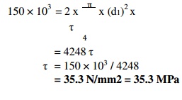
knuckle pin is in double shear, therefore load (P),

= 150 × 103 / 4248
=35.3 N/mm2 = 35.3 MPa
Failure
of the single eye or rod end in tension
The
single eye or rod end may fail in tension due to the load. We know that load (P),
150 × 103 = (d2 – d1) t × σt
= (104 –
52) 65 × σt
=3380 σt
σt = 150 × 103 / 3380
44.4 N /
mm2 = 44.4 MPa
Failure of
the single eye or rod end in shearing
The
single eye or rod end may fail in shearing due to the load. We know that load
(P), 150 × 103 = (d2 – d1) t × τ
=(104 – 52) 65 × τ
=3380 τ
= 150 × 103 / 3380
=44.4 N/mm2 = 44.4 MPa
Failure of
the single eye or rod end in crushing
The
single eye or rod end may fail in crushing due to the load. We know that load
(P), 150 × 103 = d1 × t × σc
=52 × 65 × σc
=3380 σc
σc = 150 × 103 / 3380
=44.4 N/mm2 = 44.4 MPa
Failure
of the forked end in tension
The
forked end may fail in tension due to the load. We know that load (P), 150 × 103
= (d2 – d1) 2 t1 × σt
= (104 – 52) 2 × 40 × σt
=4160 σt
σt = 150 × 103 / 4160
=36 N/mm2 = 36 MPa
Failure of
the forked end in shear
The
forked end may fail in shearing due to the load. We know that load (P),
(P), 150 × 103 = d1 × t × σc
=52 × 65 × σc
=3380 σc
σc = 150 × 103 / 3380
=44.4 N/mm2 = 44.4 MPa
Failure
of the forked end in tension
The
forked end may fail in tension due to the load. We know that load (P), 150 × 103
= (d2 – d1) 2 t1 × σt
=(104 – 52) 2 × 40 × σt
=4160 σt
σt = 150 × 103 / 4160
=36 N/mm2 = 36 MPa
Failure
of the forked end in shear
The
forked end may fail in shearing due to the load. We know that load (P),
150103 = (d2 – d1) 2 t1 × σt x τ
=(104 – 52) 2 × 40 × τ
=4160 τ
= 150 × 103 / 4160
=36 N/mm2 = 36 MPa
Failure of
the forked end in crushing
The
forked end may fail in crushing due to the load. We know that load (P), 150 ×
103 = d1 × 2t1 × σc
=52 × 2 × 40 × σc
=4160 σc
σc = 150 × 103 / 4180
=
36 N/mm2 = 36 MPa
From above,
we see that the induced stresses are less than the given design stresses,
therefore the joint is safe.
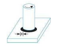
(i) A 50
mm diameter solid shaft is welded to a flat plate by 10 mm fillet weld as shown
in Fig. Find the maximum torque that the welded joint can sustain if the
maximum
shear stress intensity in the weld material is not to exceed 80 MPa.
Solution.
Given :
d = 50 mm s = 10 mm
τmax = 80
MPa = 80 N/mm2

Let T =
Maximum torque that the welded joint can sustain.
We know
that the maximum shear stress (τmax),
= 2.83T
πsd2
2.83T
= 80 × 78550 / 2.83
= 2.22 ×
106 N-mm = 2.22 kN-m
A plate 1
m long, 60 mm thick is welded to another plate at right angles to each other by
15 mm fillet weld, as shown in Fig. Find the maximum torque that the welded
joint can sustain if the permissible shear stress intensity in the weld
material is not to exceed 80 MPa. Solution.
Given:
= 1m = 1000 mm
; Thickness =
60 mm ;
= 15 mm ;
= 80 MPa
= 80 N/mm2
Let T =
Maximum torque that the welded joint can sustain We know that the maximum shear
stress (τmax),
= 4.242T / (s x l2)
= 4.242T
/ (15 x 10002)
=0.283 T / 106 T = 80 × 106 /
0.283
283 × 106
N-mm = 283 kN-m
A plate
100 mm wide and 12.5 mm thick is to be welded to another plate by means of
parallel fillet welds. The plates are subjected to a load of 50 kN. Find the
length of the weld so that the maximum stress does not exceed 56 MPa. Consider
the joint first under static loading and then under fatigue loading.
Solution.
Given:
Width =
100 mm Thickness = 12.5 mm
P = 50 kN
= 50 × 103 N ; τ = 56 MPa = 56 N/mm2
Length of
weld for static loading
Let l =
Length of weld, and
= Size of weld = Plate thickness = 12.5 mm
We know
that the maximum load which the plates can carry for double parallel fillet
welds (P),
=50 × 103 =1.414 s × l × τ
=1.414 × 12.5 × l × 56 = 990 l l = 50 × 103 / 990
=50.5 mm
Adding
12.5 mm for starting and stopping of weld run, we have
= 50.5 + 12.5
=
63 mm
Length of
weld for fatigue loading
From
Table 10.6, we find that the stress concentration factor for parallel fillet
welding is 2.7. Permissible shear stress,
τ = 56 /
2.7
=
20.74 N/mm2
We know
that the maximum load which the plates can carry for double parallel fillet
welds (P),
50
103 = 1.414 s × l × τ
=1.414 × 12.5 × l × 20.74
=367 l
= 50 × 103 / 367
=
136.2 mm
Adding
12.5 for starting and stopping of weld run, we have
= 136.2 + 12.5
=
148.7 mm
A double
riveted lap joint is made between 15 mm thick plates. The rivet diameter and
pitch are 25 mm and 75 mm respectively. If the ultimate stresses are 400 MPa in
tension, 320 MPa in shear and 640 MPa in crushing, find the minimum force per
pitch which will rupture the joint. If the above joint is subjected to a load
such that the factor of safety is 4, find out the actual stresses developed in
the plates and the rivets.
Solution.
Given :
t = 15 mm
d = 25 mm p = 75 mm
σtu = 400
MPa = 400 N/mm2
τu = 320 MPa = 320 N/mm2
σcu = 640
MPa = 640 N/mm2
Minimum
force per pitch which will rupture the joint
Since the
ultimate stresses are given, therefore we shall find the ultimate values of the
resistances of the joint. We know that ultimate tearing resistance of the plate
per pitch,
Ptu =
(p – d)t × σtu
=(75 – 25)15 × 400
=300000 N
Ultimate
shearing resistance of the rivets per pitch,
Psu = n × (π/4) x d2 x τu
=2 x (π/4) (25)2 x 320
=314200 N
Ultimate
crushing resistance of the rivets per pitch,
Pcu = n ×
d × t × σcu
=2 × 25 × 15 × 640
=480000 N
From
above we see that the minimum force per pitch which will rupture the joint is
=300000 N
or 300 kN.
Actual stresses
produced in the plates and rivets
Since the
factor of safety is 4, therefore
safe load
per pitch length of the joint = 300000 / 4
=
75000 N
Let σta τa and σca be the actual tearing, shearing
and crushing stresses produced with a safe load of 75000 N in tearing, shearing
and crushing. We know that actual tearing resistance of the plates (Pta),
75000 = (
p – d ) t × σta
=(75 – 25)15 × σta
=750 σta
σta = 75000 / 750
=
100 N/mm2 = 100 MPa.
Actual
shearing resistance of the rivets (Psa), 75000 = n × (π/4) x d2 x τa
n × (π/4) x 252 x τa
=982 τa
τa = 75000 / 982
=
76.4 N/mm2 = 76.4 MPa
Actual
crushing resistance of the rivets (Pca), 75000 = n × d × t × σca
=2 × 25 × 15 × σca
=750 σca
σca = 75000 / 750
=100 N/mm2 = 100 MPa
A double
riveted double cover butt joint in plates 20 mm thick is made with 25 mm
diameter rivets at 100 mm pitch. The permissible stresses are : σt = 120 MPa; τ = 100
MPa; σc = 150 MPa Find the efficiency of joint, taking
the strength of the rivet in double shear as twice than that of single shear.
Solution.
Given :
t = 20 mm
d = 25 mm p = 100 mm
σt = 120
MPa = 120 N/mm2
= 100 MPa = 100 N/mm2
σc = 150
MPa = 150 N/mm2
First of
all, let us find the tearing resistance of the plate, shearing resistance and
crushing resistance of the rivet.
(i)
Tearing resistance of the plate
We know
that tearing resistance of the plate per pitch
length, Pt = (p – d ) t × σt
= (100 –
25) 20 × 120
=180000 N
(ii)
Shearing resistance of the rivets
Since the
joint is double riveted butt joint, therefore the strength of two rivets in
double shear is taken. We know that shearing resistance of the rivets,
Ps = n × 2
× (π / 4) x d2 x τ
=2 x 2 x (π / 4 ) (25)2 100
=196375 N
Crushing
resistance of the rivets
Since the
joint is double riveted, therefore the strength of two rivets is taken. We know
that crushing resistance of the rivets,
Pc = n × d
× t ×σc
=2 × 25 × 20 × 150
=150000 N
Strength
of the joint = (Least of Pt, Ps and
Pc)
=
150 000 N
Efficiency
of the joint
We know
that the strength of the unriveted or solid plate,
= p × t × σt
=100 × 20 × 120
=240000 N
Efficiency
of the joint = (Least of Pt , Ps and Pc) / P =150000 / 240000
= 0.625 or
62.5%
Related Topics