Chapter: Mechanical : Design of Machine Elements : Design of Temporary and Permanent Joints
Design of Temporary and Permanent Joints
DESIGN
OF TEMPORARY AND PERMANENT JOINTS
Welded
Joints
A
welded joint is a permanent joint which is obtained by the fusion of the edges
of the two parts to be joined together, with or without the application of
pressure and a filler material. The heat required for the fusion of the
material may be obtained by burning of gas (in case of gas welding) or by an
electric arc (in case of electric arc welding). The latter method is
extensively used because of greater speed of welding.
Welding
is extensively used in fabrication as an alternative method for casting or
forging and as a replacement for bolted and riveted joints. It is also used as
a repair medium e.g. to reunite metal at a crack, to build up a small part that
has broken off such as gear tooth or to repair a worn surface such as a bearing
surface.
Advantages and Disadvantages of Welded Joints over Riveted Joints
Following are the advantages and
disadvantages of welded joints over riveted joints.
Advantages
The
welded structures are usually lighter than riveted structures. This is due to
the reason, that in welding, gussets or other connecting components are not
used.
The
welded joints provide maximum efficiency (may be 100%) which is not possible in
case of riveted joints.
Alterations
and additions can be easily made in the existing structures.
As
the welded structure is smooth in appearance, therefore it looks pleasing.
In
welded connections, the tension members are not weakened as in the case of
riveted joints.
A
welded joint has a great strength. Often a welded joint has the strength of the
parent metal itself.
Sometimes,
the members are of such a shape (i.e. circular steel pipes) that they afford
difficulty for riveting. But they can be easily welded.
The
welding provides very rigid joints. This is in line with the modern trend of
providing rigid frames.
Disadvantages
Since
there is an uneven heating and cooling during fabrication, therefore the
members may get distorted or additional stresses may develop.
It
requires a highly skilled labour and supervision.
Since
no provision is kept for expansion and contraction in the frame, therefore
there is a possibility of cracks developing in it.
The
inspection of welding work is more difficult than riveting work.
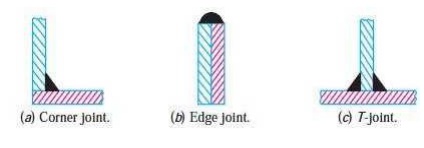
Types
of Welded Joints
Following two types of welded joints
are important from the subject point of view:
Lap
joint or fillet joint, and
Butt
joint.
Lap
Joint
The lap joint or the fillet joint is
obtained by overlapping the plates and then welding the edges of the plates.
The cross-section of the fillet is approximately triangular. The fillet joints
may be
Single
transverse fillet,
Double
transverse fillet, and
Parallel
fillet joints.
The fillet joints are shown in Fig.
A single transverse fillet joint has the disadvantage that the edge of the
plate which is not welded can buckle or warp out of shape.
Butt
Joint
The butt joint is obtained by
placing the plates edge to edge as shown in Fig. 10.3. In butt welds, the plate
edges do not require bevelling if the thickness of plate is less than 5 mm. On
the other hand, if the plate thickness is 5 mm to 12.5 mm, the edges should be
bevelled to V or U-groove on both sides.
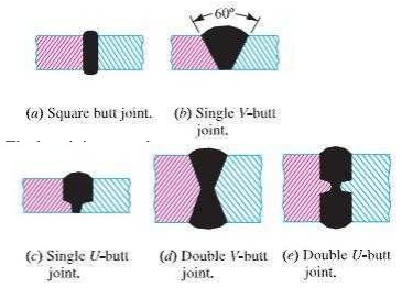
The butt joints may be
Square
butt joint,
Single
V-butt joint
Single
U-butt joint,
Double
V-butt joint, and
Double
U-butt joint.
Riveted
Joints
A
rivet is a short cylindrical bar with a head integral to it. The cylindrical
portion of the rivet is called shank or body and lower portion of shank is known as tail, as shown in Fig. The rivets are
used to make permanent fastening between the plates such as in structural work,
ship building, bridges, tanks and boiler shells. The riveted joints are widely
used for joining light metals. The fastenings (i.e. joints) may be classified
into the following two groups:
Permanent
fastenings, and
Temporary
or detachable fastenings.
Types
of Riveted Joints
Following are the two types of
riveted joints, depending upon the way in which the plates are connected.
Lap
joint, and
Butt
joint.
Lap
Joint
A
lap joint is that in which one plate overlaps the other and the two plates are
then riveted together.
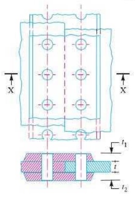
Butt
Joint
A
butt joint is that in which the main plates are kept in alignment butting (i.e.
touching) each other and a cover plate (i.e. strap) is placed either on one
side or on both sides of the main plates. The cover plate is then riveted
together with the main plates. Butt joints are of the following two types:
Single
strap butt joint, and
Double
strap butt joint.
In
a single strap butt joint, the edges of the main plates butt against each other and
only one cover plate is placed on one side of the main plates and then riveted
together.
In
a double strap butt joint, the edges of the main plates butt against each other and two
cover plates are placed on both sides of the main plates and then riveted
together.
In
addition to the above, following are the types of riveted joints depending upon
the number of rows of the rivets.
Single
riveted joint, and
Double
riveted joint.
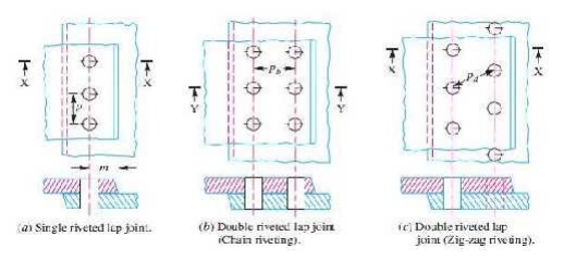
A single riveted joint is that in which
there is a single row of rivets in a lap joint as shown in Fig. (a) and there
is a single row of rivets on each side in a butt joint as shown in Fig.
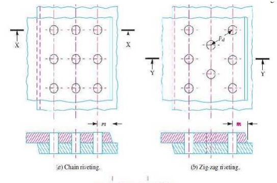
A
double riveted joint
is that in which there are two rows of rivets in a lap joint as shown in Fig.
(b) and (c) and there are two rows of rivets on each side in a butt joint as
shown in Fig.
Important
Terms Used in Riveted Joints
The following terms in connection
with the riveted joints are important from the subject point of view :
1. Pitch. It is the distance from the centre of one rivet to the
centre of the next rivet measured parallel to the seam as shown in Fig. 9.6. It
is usually denoted by p.
Back pitch. It
is the perpendicular distance between the centre lines of the successive rows
as shown in
Fig. It is usually denoted by pb.
Diagonal pitch. It
is the distance between the centres of the rivets in adjacent rows of zig-zag riveted joint as shown in Fig. 9.6.
It is usually denoted by pd.
Margin or marginal pitch. It is the distance between the
centre of rivet hole to the nearest edge of the plate as shown in Fig. 9.6. It is usually denoted by
m.
Efficiency
of a Riveted Joint
The
efficiency of a riveted joint is defined as the ratio of the strength of
riveted joint to the strength of the un-riveted or solid plate.
We have already discussed that
Strength of the riveted joint =
Least of Pt, Ps and Pc
Strength of the un-riveted or solid
plate per pitch length,
P = p × t × σt
Efficiency of the riveted joint,
η = (Least of Pt , Ps and Pc) / (p ×
t × σt)
where p = Pitch of the rivets,
t = Thickness of the plate, and
σt = Permissible tensile stress of
the plate material.
Related Topics