Chapter: Mechanical : Design of Machine Elements : Design of Shafts and Couplings
Solved Problems: Design of Shafts and Couplings
Given :
N = 200 r.p.m. ;
P = 20 kW = 20 × 103 W; τ= 42 MPa = 42 N/mm2
Let d = Diameter of the shaft.
We know that torque transmitted by the shaft,
= P∗ 60
2πN 3
= 20 ∗ 10 ∗60 2π∗ 200
= 5 N-m
= 955 × 103 N-mm
We also know that torque transmitted by the shaft ( T ),
955 × 103 = π *
τ*d3
16
d3 = 955 × 103 / 8.25
= 115 733 or d
= 48.7 say 50 mm
P = 20 kW = 20 × 103 W N = 200 r.p.m.
τu = 360 MPa = 360 N/mm2 F.S. = 8
k = di / do = 0.5 We know that the allowable shear stress,
= (τu / FOS)
360/8
45 N/mm2
Diameter of the solid shaft
Let d = Diameter of the solid shaft.
We know that torque transmitted by the shaft,
T = P∗ 60 / 2πN
20 x103 x60 / 2πN
955 N-m = 955 × 103 N-mm
We also know that torque transmitted by the solid shaft (T), 955 × 103 = π *
τ*d3
16
d3 = 955 × 103 / 8.84
= 108 032 or
d = 47.6 say 50 mm
Diameter of hollow shaft
Let di = Inside diameter,
and do = Outside
diameter.
We know that the torque transmitted by the hollow shaft ( T ),
955 × 103 = π * τ*(do)3 (1- k4)
16
(do)3 = 955 × 103 / 8.3 = 115 060 or do
do = 48.6 say 50 mm
and di = 0.5 do
= 0.5 × 50
A solid circular shaft is subjected to a bending moment of 3000 N-m and a torque of 10 000 N-m. The shaft is made of 45 C 8 steel having ultimate tensile stress of 700 MPa and an ultimate shear stress of 500 MPa. Assuming a factor of safety as 6, determine the diameter of the shaft.
Solution.
Given :
M = 3000 N-m = 3 × 10⁶ N-mm ;
T = 10 000 N-m = 10 × 106 N-mm ;
σtu = 700 MPa = 700 N/mm2 ;
τu = 500 MPa = 500 N/mm2
We know that the allowable tensile stress,
σt or σb = σtu
FOS = 700/6
= 116.7 N/mm2
and allowable shear stress,
τ = τ u
FOS
500/6
83.3 N/mm2
Let d = Diameter of the shaft in mm.
According to maximum shear stress theory, equivalent twisting moment,
Te = √M^2 + T^2
= √(3 × 10⁶ )2 + (10 × 106 )2
= 10.44 × 10⁶ N-mm
We also know that equivalent twisting moment (Te),
10.44 × 106 = π * τ*d3
16
d3 = 10.44 × 10⁶ / 16.36 = 0.636 × 10⁶ or
= 86 mm
A 15 kW, 960 r.p.m. motor has a mild steel shaft of 40 mm diameter and the extension being 75 mm. The permissible shear and crushing stresses for the mild steel key are 56 MPa and 112 MPa. Design the keyway in the motor shaft extension. Check the shear strength of the key against the normal strength of the shaft.
Solution.
Given :
P = 15 kW = 15 × 103 W N = 960 r.p.m.
d = 40 mm
= 75 mm
τ = 56 MPa = 56 N/mm2
σc = 112 MPa = 112 N/mm2
We know that the torque transmitted by the motor,
T = P∗ 60 2πN
149 N-m
149 × 103 N-mm
Let w = Width of keyway or key.
Considering the key in shearing. We know that the torque transmitted (T),
This width of keyway is too small. The width of keyway should be at least d / 4.
=10 mm
Since σc = 2 τ, therefore a square key of w = 10 mm and t = 10 mm is adopted. According to H.F. More, the shaft strength factor,
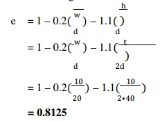
= 0.8125
Strength of the shaft with keyway = π * τ*d3*e
16
= 571 844 N
Shear strength of the key = l . w. τ.(d/2)
= 75 x 10 x 56 x (40/2)
= 840000 N
eyShear s t ren gt h of the k = 840000
Normal streng th of the shaft = 571844
Design a clamp coupling to transmit 30 kW at 100 r.p.m. The allowable shear stress for the shaft and key is 40 MPa and the number of bolts connecting the two halves are six. The permissible tensile stress for the bolts is 70 MPa. The coefficient of friction between the muff and the shaft surface may be taken as 0.3.
Solution.
Given :
P = 30 kW = 30 × 103 W N = 100 r.p.m.
τ = 40 MPa = 40 N/mm2 n = 6
σt = 70 MPa = 70 N/mm2
= 0.3
Design for shaft
Let d = Diameter of shaft.
We know that the torque transmitted by the shaft,
T = 30x103x60 / (2π x 100)
= 2865 N-m
We also know that the torque transmitted by the shaft (T), 2865 × 103 = π * τ*d3
= π * 40*d3
d3 = 2865 × 103 / 7.86 = 365 × 103
d = 71.4 say 75 mm
2. Design for muff
We know that diameter of muff,
= 2d + 13 mm = 2 × 75 + 13
163 say 165 mm
Total length of the muff, L = 3.5 d
The width and thickness of the key for a shaft diameter of 75 mm are as follows
: Width of key, w = 22 mm
Thickness of key, t = 14 mm
Length of key = Total length of muff = 262.5 mm
4. Design for bolts
Let db = Root or core diameter of bolt. We know that the torque transmitted (T),
2865 × 103 = (π2 / 16) × µ(db )2 σt ×n × d
= (π2 / 16) × 0.3 (db )2 x 70 × 6 × 75 (db )2 = 2865 × 103 / 5830 = 492
db = 22.2 mm
From Table 11.1, we find that the standard core diameter of the bolt for coarse series is 23.32 mm and the nominal diameter of the bolt is 27 mm (M 27).
Two 35 mm shafts are connected by a flanged coupling. The flanges are fitted with 6 bolts on 125 mm bolt circle. The shafts transmit a torque of 800 N-m at 350 r.p.m. For the safe stresses mentioned below,
Safe stress for cast iron coupling = 10 MPa Safe stress for key material = 46 MPa Solution.
Given :
d = 35 mm n = 6
D1 = 125 mm
T = 800 N-m = 800 × 103 N-mm N = 350 r.p.m.;
s = 63 MPa = 63 N/ mm2
b = 56 MPa = 56 N/ mm2
c = 10 MPa = 10 N/mm2
k = 46 MPa = 46 N/ mm2
Diameter of bolts
Let d1 = Nominal or outside diameter of bolt.
We know that the torque transmitted ( T ),
800 × 103 = π (d1)2 τb x n x
(D1/2)
4
(d1)2 = 800 × 103 / 16495 = 48.5
d1 = 6.96 say 8 mm
2. Thickness of flanges
Let tf = Thickness of flanges.
We know that the torque transmitted (T ),
800 × 103 = π D^2 x τc x tf
16
tf = 800 × 103 / 76980
= 10.4 say 12 mm
3. Key dimensions
From Table 13.1, we find that the proportions of key for a 35 mm diameter shaft
are : Width of key, w = 12 mm
and thickness of key, t = 8 mm
The length of key ( l ) is taken equal to the length of hub (L). l = L = 1.5 d
= 1.5 × 35
= 52.5 mm
Let us now check the induced shear stress in the key. We know that the torque transmitted (T ), 800 × 103 = l x w x τk x (d/2)
τk = 800 × 103 / 11025
= 72.5 N/mm2
Since the induced shear stress in the key is more than the given safe stress (46 MPa), therefore let us find the length of key by substituting the value of τk = 46 MPa in the above equation, i.e.
800 × 103 = l x 12 x 46 x (35/2) = 9660 l
= 800 × 103 / 9660
= 82.8 say 85 mm
4. Hub length
Since the length of key is taken equal to the length of hub, therefore we shall take hub length,
L = l = 85 mm
5. Power transmitted
We know that the power transmitted,
= T x 2πN / 60
800 x 2 π x 350 /60
29 325 W = 29.325 kW
Related Topics