Chapter: Mechanical : Design of Machine Elements : Design of Shafts and Couplings
Design of Shafts and Couplings
DESIGN OF
SHAFTS AND COUPLINGS
Material
Used for Shafts
The
material used for shafts should have the following properties :
It should
have high strength.
It should
have good machinability.
It should
have low notch sensitivity factor.
It should
have good heat treatment properties.
It should
have high wear resistant properties.
Types of Shafts
The
following two types of shafts are important from the subject point of view :
1. Transmission shafts. These
shafts transmit power between the source and the machines absorbing power. The
counter shafts, line shafts, over head shafts and all factory shafts are
transmission shafts. Since these shafts carry machine parts such as pulleys,
gears etc., therefore they are subjected to bending in addition to twisting.
Machine shafts. These
shafts form an integral part of the machine itself. The crank shaft is an
example of machine shaft.
Stresses in Shafts
The
following stresses are induced in the shafts :
Shear stresses due to the transmission of torque
(i.e. due to torsional load).
Bending stresses (tensile or compressive) due to
the forces acting upon machine elements like gears, pulleys etc. as well as due
to the weight of the shaft itself.
Stresses due to combined torsional and bending
loads
Design of Shafts
The
shafts may be designed on the basis of
Strength,
and
Rigidity
and stiffness.
In
designing shafts on the basis of strength, the following cases may be
considered :
Shafts subjected to twisting moment or torque only,
Shafts subjected to bending moment only,
Shafts
subjected to combined twisting and bending moments, and
Shafts subjected to axial loads in addition to
combined torsional and bending loads
Shafts
Subjected to Bending Moment Only
When the shaft is subjected to a bending moment
only, then the maximum stress (tensile or compressive) is given by the bending
equation. We know that
M/I
= σb/y
where M = Bending moment,
I =
Moment of inertia of cross-sectional area of the shaft about the axis of
rotation,
σb =
Bending stress, and
y =
Distance from neutral axis to the outer-most fibre.
Shafts
Subjected to Twisting Moment Only
When the shaft is subjected to a twisting moment
(or torque) only, then the diameter of the shaft may be obtained by using the
torsion equation. We know that
T
/J = τ/r
where T = Twisting moment (or torque) acting upon
the shaft,
J = Polar
moment of inertia of the shaft about the axis of rotation, τ = Torsional shear
stress, and
r =
Distance from neutral axis to the outer most fibre
d / 2;
where d is the diameter of the shaft.
Shafts Subjected to Combined Twisting Moment and
Bending Moment
When the
shaft is subjected to combined twisting moment and bending moment, then the
shaft
must be
designed on the basis of the two moments simultaneously. Various theories have
been suggested to account for the elastic failure of the materials when they
are subjected to various types of combined stresses. The following two theories
are important from the subject point of view:
Maximum shear stress theory or Guest's theory. It
is used for ductile materials such as mild steel.
Maximum normal stress theory or Rankine’s theory.
It is used for brittle materials such as cast iron.
Let τ =
Shear stress induced due to twisting moment, and
σb =
Bending stress (tensile or compre ssive) induced due to bending moment.
Shafts
Subjected to Fluctuating Loads
In the
previous articles we have assumed that the shaft is subjected to constant
torque and bending moment. But in actual practice, the shafts are subjected to
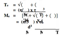
fluctuating torque and bending moments. In order to design such shafts like
line shafts and counter shafts, the combined shock and fatigue factors must be
taken into account for the computed twisting moment (T ) and bending moment (M
). Thus for a shaft subjected to c ombined ben ding and torsion, the equivalent
twisting moment,
KEYS:
A key is a piece of mild steel inserted between the
shaft and hub or boss of the pulley to connect these together in order to
prevent relative motion between them. It is always inserted parallel to the
axis of the shaft. Keys are used as temporary fastenings and are subjected to
considerable crushing and shearing stresses. A keyway is a slot or recess in a
shaft and hub of the pulley to accommodate a key.
Types
of Keys
The
following types of keys are important from the subject point of view:
Sunk keys,
Saddle keys,
Tangent keys,
Round keys,
Splines.
Shaft Coupling
Shafts are usually available up to 7 metres length
due to inconvenience in transport. In order to have a greater length, it
becomes necessary to join two or more pieces of the shaft by means of a
coupling.
Shaft
couplings are used in machinery for several purposes, the most common of which
are the following :
To provide for the connection of shafts of units
that are manufactured separately such as a motor and generator and to provide
for disconnection for repairs or alternations.
To provide for misalignment of the shafts or to
introduce mechanical flexibility.
To reduce the transmission of shock loads from one
shaft to another.
To introduce protection against overloads.
It should have no projecting parts.
Shaft
couplings are divided into two main groups as follows:
1. Rigid
coupling.
It is used to connect two shafts which are
perfectly aligned. Following types of rigid coupling are important from the
subject point of view:
Sleeve or muff coupling.
Clamp or split-muff or compression coupling, and
Flange coupling.
2. Flexible
coupling.
It is used to connect two shafts having both
lateral and angular misalignment. Following types of flexible coupling are
important from the subject point of view :
Bushed pin type coupling,
Universal coupling, and
Oldham coupling.
Related Topics