Chapter: Mechanical : Strength of Materials : Transverse Loading On Beams And Stresses In Beam
Shear force and Bending Moment in beams
Shear force and
Bending Moment in beams
Concept of Shear
Force and Bending moment in beams:
When the beam is loaded
in some arbitrarily manner, the internal forces and moments are developed and
the terms shear force and bending moments come into pictures which are helpful
to analyze the beams further. Let us define these terms
Now let us consider the
beam as shown in fig 1(a) which is supporting the loads P1, P2, P3 and is
simply supported at two points creating the reactions R1 and R2respectively.
Now let us assume that the beam is to divided into or imagined to be cut into
two portions at a section AA. Now let us assume that the resultant of loads and
reactions to the left of AA is
„F' vertically upwards,
and equilibrium,since thusthe resultant of forces to the right of A a shear
force. The shearing force at any x-section of a beam represents the tendency
for the portion of the beam to one side of the section to slide or shear
laterally relative to the other portion.
Therefore, now we
are in a
position t
At any x-section of a
beam, the shear for components of the forces acting on either side of the
x-section.
Sign Convention for Shear Force:
The usual sign
conventions to be followed for the shear forces have been illustrated in
figures 2 and 3.
Bending Moment:
Let
us again consider the beam which is simply supported at the two prints,
carrying loads P1, P2 and P3 and having the reactions R1 and R2 at the supports
Fig 4. Now, let us imagine that the beam is cut into two potions at the
x-section AA. In a similar manner, as done for the case of shear force, if we
say that the resultant moment about the section AA of all the loads and
reactions to the left of the x-section at AA is M in C.W direction, then moment
of forces to the right of x-section AA must be „M' in C. moment and is
abbreviated as B.M. Now one can define the bending moment to be simply as the
algebraic sum of the moments about an x-section of all the forces acting on
either side of the section
Sign Conventions for the Bending Moment:
For the bending moment, following sign
conventions may be adopted as indicated in Fig 5
and Fig 6.
Some times, the terms
„Sagging' and negative bending moments respectively.
Bending Moment and Shear Force Diagrams:
The diagrams which
illustrate the variations in B.M and S.F values along the length of the beam
for any fixed loading conditions would be helpful to analyze the beam further.
Thus, a shear force
diagram is a graphical plot, which depicts how the internal shear force „F'
varieslength ofalongbeam.Ifx dentotesthethe length of the beam, then F is
function x i.e. F(x).
Similarly a bending
moment diagram is a graphical plot which depicts how the internal bending
moment „M' varies along theM(x)l.
Basic Relationship Between The Rate of
Loading, Shear Force and Bending Moment:
The construction of the
shear force diagram and bending moment diagrams is greatly simplified if the
relationship among load, shear force and bending moment is established.
Let us consider a simply supported beam
AB carrying a uniformly distributed load w/length.
Let us imagine to cut a
short slice o from the origin „0'.
Let us detach this portion of the beam
and draw its free body diagram.
The forces acting on
the free body diagram of the detached portion of this loaded beam are the
following
•
The
shearingdFat theforcesectionxandFx + andxrespectivelyF+.
• The bending
momentdx beatMandtheM+dMsectionsrespectively.
• Force due to external
loading, if „ total loading on this slice of length dx is w. dx,
which is approximately acting through the centre „c'. If
theobeuniformlyloadingdistributed thenisit wouldassumedpassexactly through the
centre „c'.
This small element must be in
equilibrium under the action of these forces and couples.
Now let us
take the moments
at the po
Conclusions: From
the above relations,the following important conclusions may be drawn
•
From Equation (1), the area of the basic
calculus is the bending moment diagram
•
The
slope of bending
moment diagram
Thus, if F=0; the slope
of the bending moment diagram is zero and the bending moment is therefore
constant.'
•
The
maximum or minimum
Bending mome
The slope of the shear
force diagram is equal to the magnitude of the intensity of the distributed
loading at any position along the beam. The –ve sign is as a consequence of our
particular choice of sign conventions
Procedure for drawing shear force and
bending moment diagram:
Preamble:
The advantage of
plotting a variation of shear force F and bending moment M in a beam as a
function of „x' measured from one end maximum absolute value of shear force and
bending moment.
Further, the
determination of valueramount importance so as to determine the value of
deflection of beam subjected to a given loading.
Construction of shear force and bending
moment diagrams:
A shear force diagram
can be constructed from the loading diagram of the beam. In order to draw this,
first the reactions must be determined always. Then the vertical components of
forces and reactions are successively summed from the left end of the beam to
preserve the mathematical sign conventions adopted. The shear at a section is
simply equal to the sum of all the vertical forces to the left of the section.
When the successive
summation process is used, the shear force diagram should end up with the
previously calculated shear (reaction at right end of the beam. No shear force
acts through the beam just beyond the last vertical force or reaction. If the
shear force diagram closes in this fashion, then it gives an important check on
mathematical calculations.
The bending moment
diagram is obtained by proceeding continuously along the length of beam from
the left hand end and summing up the areas of shear force diagrams giving due
regard to sign. The process of obtaining the moment diagram from the shear
force diagram by summation is exactly the same as that for drawing shear force
diagram from load
diagram.
It may also be observed
that a constant shear force produces a uniform change in the bending moment,
resulting in straight line in the moment diagram. If no shear force exists
along a certain portion of a beam, then it indicates that there is no change in
moment takes place. It may also further observe that dm/dx= F therefore, from
the fundamental theorem of calculus the maximum or minimum moment occurs where
the shear is zero. In order to check the validity of the bending moment
diagram, the terminal conditions for the moment must be satisfied. If the end
is free or pinned, the computed sum must be equal to zero. If the end is built
in, the moment computed by the summation must be equal to the one calculated
initially for the reaction. These conditions must always be satisfied.
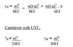
Cantilever beams - problems
Cantilever with a point load at the free
end:
Mx
= - w.x
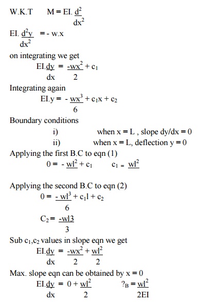
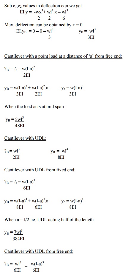
A cantilever
of length carries
a conc
Draw shear force and bending moment.
Solution:
At a section a distance
x from free end consider the forces to the left, then F = -W (for all values of
x) -ve sign means the shear force to the left of the x-section are in downward
direction and therefore negative
Taking moments about the section gives
(obviously to the left of the section)
M = -Wx (-ve sign means
that the moment on the left hand side of the portion is in the anticlockwise
direction and is therefore taken as –ve according to the sign convention)
so that the maximum bending moment
occurs at the fixed end i.e. M = -W l
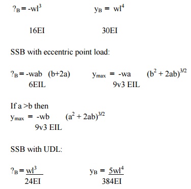
Simply supported beam -problems
Simply
supported beam subjected to a central load (i.e. load acting at the mid-way)
By symmetry the
reactions at the two supports would be W/2 and W/2. now consider any section
X-X from the left end then, the beam is under the action of following forces.
.So the shear force at any X-section
would be = W/2 [Which is constant upto x < l/2]
If we consider another section Y-Y which
is beyond l/2 then
for all values greater = l/2
SSB with central point load:
Overhanging beams - problems
In
the problem given below, the intensity of loading varies from q1 kN/m at one
end to the q2 kN/m at the other end.This problem can be treated by considering
a U.d.i of intensity q1 kN/m over the entire span and a uniformly varying load
of 0 to ( q2- q1)kN/m over the entire span and then super impose teh two
loadings.
Point of Contraflexure:
Consider the loaded
beam a shown below along with the shear force and Bending moment diagrams for
It may be observed that this case, the bending moment diagram is completely
positive so that the curvature of the beam varies along its length, but it is
always concave upwards or sagging.However if we consider a again a loaded beam
as shown below along with the S.F and B.M diagrams, then
It may be noticed that for the beam
loaded as in this case,
The bending moment
diagram is partly positive and partly negative.If we plot the deflected shape
of the beam just below the bending moment
This diagram shows that L.H.S
of the beam
„sags'
The point C on the beam
where the curvature changes from sagging to hogging is a point of
contraflexure.
OR
It corresponds to a
point where the bending moment changes the sign, hence in order to find the
point of contraflexures obviously the B.M would change its sign when it cuts
the X-axis therefore to get the points of contraflexure equate the bending
moment equation equal to zero.The fibre stress is zero at such sections
Note: there can
be more than one point of contraflexure 2.4Stresses in beams
Preamble:
When
a beam having an arbitrary cross section is subjected to a transverse loads the
beam will bend. In addition to bending the other effects such as twisting and
buckling may occur, and to investigate a problem that includes all the combined
effects of bending, twisting and buckling could become a complicated one. Thus
we are interested to investigate the bending effects alone, in order to do so,
we have to put certain constraints on the geometry of the beam and the manner
of loading.
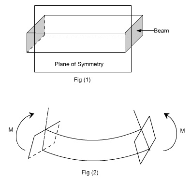
Assumptions:
The
constraints put on the geometry would form the assumptions:
1. Beam
is initially straight , and has a constant cross-section.
2.
Beam is made of homogeneous material
and the beam has a longitudinal plane of symmetry.
3. Resultant
of the applied loads lies in the plane of symmetry.
4.
The geometry of the overall member is
such that bending not buckling is the primary cause of failure.
5. Elastic
limit is nowhere exceeded and ‘E'issame in tension and compression.
6. Plane
cross - sections remains plane before and after bending.
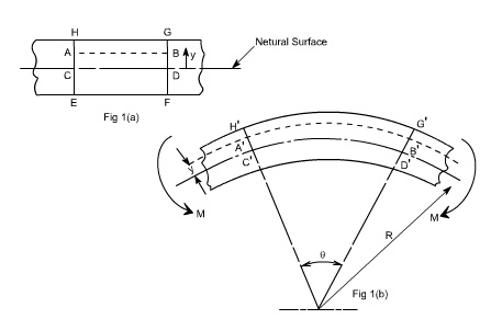
Let us consider a beam
initially unstressed as shown in fig 1(a). Now the beam is subjected to a
constant bending moment (i.e. „ obtained by applying equal couples at each end.
The beam will bend to the radius R as shown in Fig 1(b)
As a result of this bending, the top fibers
of the beam will be subjected to tension and the bottom to compression it is
reasonable to suppose, therefore, that some here between the two
there are points at which the stress is zero. The locus of all such points is
known as neutral axis . The radius of curvature R is then measured to this
axis. For symmetrical sections the N. A. is the axis of symmetry but
what ever the section N. A. will always pass through the centre of the area or
centroid.
As
we are aware of the fact internal reactions developed on any cross-section of a
beam may consists of a resultant normal force, a resultant shear force and a
resultant couple. In order to ensure that the bending effects alone are
investigated, we shall put a constraint on the loading such that the resultant
normal and the resultant shear forces are zero on any cross-section
perpendicular to the longitudinal axis of the member, That means F = 0 since or
M = constant.
Thus, the zero shear force means that the bending moment is constant or the bending is same at every cross-section of the beam. Such a situation may be visualized or envisaged when the beam or some portion of the beam, as been loaded only by pure couples at its ends. It must be recalled that the couples are assumed to be loaded in the plane of symmetry.
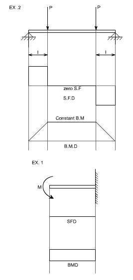
When a member is loaded
in such a fashion it is said to be in pure bending. The examples of pure
bending have been indicated in EX 1and EX 2 as shown below :
When a beam is
subjected to pure bending are loaded by the couples at the ends, certain
cross-section gets deformed and we shall have to make out the conclusion that,
1.Plane
sections originally perpendicular to longitudinal axis of the beam remain plane
and perpendicular to the longitudinal axis even after bending , i.e. the
cross-section A'E', B'F' ( refer Fig 1(a) ) do not get warped or curved.
2.
In the deformed section, the planes of
this cross-section have a common intersection i.e. any time originally parallel
to the longitudinal axis of the beam becomes an arc of circle.
We know that when a
beam is under bending the fibres at the top will be lengthened while at the
bottom will be shortened provided the bending moment M acts at the ends. In
between these there are some fibres which remain unchanged in length that is
they are not strained, that is they do not carry any stress. The plane
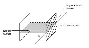
containing such fibres is called neutral surface.
The line of
intersection between the neutral surface and the transverse exploratory section
is called the neutral axisNeutral axis (N A) .
Bending Stresses in Beams or Derivation
of Elastic Flexural formula :
In order to compute the
value of bending stresses developed in a loaded beam, let us consider the two
cross-sections of a beam HE and GF , originally parallel as shown
in fig 1(a).when the beam is to bend it is assumed that these sections remain
parallel i.e. H'E' and G'F' , the final position
of the sections, are still straight lines, they then subtend some angle q.
Consider now fiber AB in the material, at adistance y from the N.A, when the beam bends this will stretch to A'B'
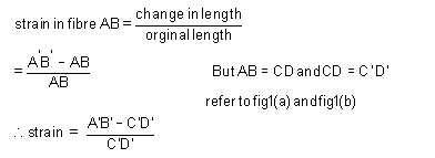
Since CD and C'D' are on the neutral axis and it is assumed that the Stress on the neutral axis zero. Therefore, there won't be any strain on the neutral axis.
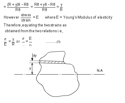
Consider any arbitrary a cross-section of beam, as shown above now the strain on a fibre at a distance „y' from the N.A, is given b Now the termis the property of the material and is called as a second moment of area of the cross-section and is denoted by a symbol I.
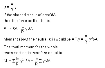
Therefore
M/I = sigma/y = E/R
This
equation is known as the Bending Theory Equation.The above proof has involved
the assumption of pure bending without any shear force being present. Therefore
this termed as the pure bending equation. This equation gives distribution of
stresses which are normal to cross-section i.e. in x-direction.
Stress variation along the
length and in the beam section Bending Stress and Deflection Equation
In this section, we consider
the case of pure bending; i.e., where only bending stresses exist as a
result of applied
bending moments. To
develop the theory,
we will take
the phenomenological approach to develop whatEuleris-Bernoullicalledtheoryof beamth
bending.”Geometry: Consider a long slender straight beam of length L and
cross-sectional area A. We assume the beam is
prismatic or nearly so. The length dimension is large compared to the
dimensions of the cross-section. While
the cross-section may be any shape, we
will assume that it is symmetric about the y axis Loading: For our purposes, we
will consider shear forces or distributed loads that are applied in the y
direction only (on the surface of the beam) and moments about the z-axis. We
have consider examples of such loading in ENGR 211 previously and some examples
are shown below:
Kinematic Observations: In
order to obtain a “fee beam subjected to pure bending loads,
it is informative to conduct an experiment. Consider a rectangular lines
have been scribed
on the beam’ bottom surfaces (and thus parallel to
a centroidally placed x-axis along the length of the beam). Lines
are also scribed
around the circumference
of the beam
so that they
are perpendicular to the longitudinals (these circumferential lines form
flat planes as shown).
The longitudinal and circumferential
lines form a square grid on the surface. The beam is now bent by moments at
each end as shown in the lower photograph. After loading, we note
that
the top line has stretched and the bottom line has shortened (implies that
there is strain exx). If measured carefully, we see that the
longitudinal line at the center has not changed length (implies that exx
= 0 at y = 0). The longitudinal lines now appear to form concentric
circular lines.
We
also note that the vertical lines originally perpendicular to the longitudinal
lines remain straight
and
perpendicular to the longitudinal lines. If measured carefully, we will see
that the vertical lines remain approximately the same length (implies eyy
= 0). Each of the vertical lines (as well as the planes they form) has rotated
and, if extended downward, they will pass through a common point that forms the
center of the concentric longitudinal lines (with some radius ?). The
flat planes originally normal to the longitudinal axis remain essentially flat
planes and remain normal to the deformed longitudinal lines. The squares on the
surface are now quadrilaterals and each appears to have tension (or
compression) stress in the longitudinal direction (since the horizontal lines
of a square have changed length). However, in pure bending we make the
assumption that. If the x-axis is along the length of beam and the y-axis
is normal to the beam, this suggests that we have an axial normal stress sxx
that is tension above the x-axis and compression below the y-axis.
The remaining normal stresses syy and szz will generally be
negligible for pure bending about the z-axis. For pure bending, all
shear stresses are assumed to be zero. Consequently, for pure bending, the
stress matrix reduces to zero
Related Topics