Chapter: Civil : Mechanics Of Solids : Transverse Loading On Beams And Stresses In Beam
Shear force and Bending Moment in beams
Shear force and Bending Moment in beams
Concept of Shear Force and Bending moment in
beams:
When the beam is loaded in some
arbitrarily manner, the internal forces and moments are developed and the terms
shear force and bending moments come into pictures which are helpful to analyze
the beams further. Let us define these terms
Now let us consider the beam as shown in fig 1(a) which is
supporting the loads P1, P2, P3 and is simply supported at two points creating
the reactions R1 and R2respectively. Now let us assume that the beam is to
divided into or imagined to be cut into two portions at a section AA. Now let us
assume that the resultant of loads and reactions to the left of AA is �F'
vertically upwards, and
since the entire beam is to
remain in equilibrium, thus the resultant of forces to the right of AA must
also be F, acting downwards. This forces �F' is as a shear force. The shearing
force at any x-
section of a beam represents the
tendency for the portion of the beam to one side of the section to slide or
shear laterally relative to the other portion.
Therefore, now we are in a position to define the
shear force �F' to as follows:
At any x-section
of a beam, the shear force �F' is the algebraic sum of all the lateral components of the
forces acting on either side of the x-section.
Sign Convention for Shear Force:
The usual sign conventions to be
followed for the shear forces have been illustrated in figures 2 and 3.
Bending Moment:
Let us again consider the beam
which is simply supported at the two prints, carrying loads P1, P2 and P3 and
having the reactions R1 and R2 at the supports Fig 4. Now, let us imagine that
the beam is cut into two potions at the x-section AA. In a similar manner, as
done for the case of shear force, if we say that the resultant moment about the
section AA of all the loads and
reactions to the left of the
x-section at AA is M in C.W direction, then moment of forces to the right of x-section
AA must be �M' in C.C.W. Then �M' is called as the Bending moment and
is
abbreviated as B.M. Now one can
define the bending moment to be simply as the algebraic sum of the moments
about an x-section of all the forces acting on either side of the section
Sign Conventions for the Bending Moment:
For the bending moment, following
sign conventions may be adopted as indicated in Fig 5 and Fig 6.
Some times, the terms
�Sagging' and Hogging are generally used for the positive and negative bending
moments respectively.
Bending Moment and Shear Force Diagrams:
The diagrams which illustrate the
variations in B.M and S.F values along the length of the beam for any fixed
loading conditions would be helpful to analyze the beam further.
Thus,
a shear force diagram is a graphical plot, which depicts how the internal shear
force �F'
varies
along the length of beam. If x dentotes the length of the beam, then F is
function x i.e. F(x).
Similarly a bending moment
diagram is a graphical plot which depicts how the internal bending moment
�M' varies along the length of the beam. Again M is a
function x i.e. M(x).
Basic Relationship Between The Rate of Loading,
Shear Force and Bending Moment:
The construction of the shear
force diagram and bending moment diagrams is greatly simplified if the
relationship among load, shear force and bending moment is established.
Let us consider a simply
supported beam AB carrying a uniformly distributed load w/length. Let us
imagine to cut a short slice of length dx cut out from this loaded beam at
distance �x' from the origin �0'.
Let us detach this portion of the beam and draw its free body
diagram.
The forces acting on the free
body diagram of the detached portion of this loaded beam are the following
� The
shearing force F and F+ dF at the section x and x +
dx
respectively.
� The
bending moment at the sections x and x + dx be M
and M + dM respectively.
�
Force due to external loading, if �w' is
the mean rate of loading per unit length then the total loading
on this slice of length dx is w. dx, which is
approximately acting through the centre �c'.
If the loading is assumed to be
uniformly distributed then it would pass exactly through the centre
�c'.
This small element must be in equilibrium under the action of
these forces and couples.
Now let us take the moments at the point �c'. Such
that
Conclusions: From the above
relations,the following important conclusions may be drawn
�
From Equation (1), the area of the shear
force diagram between any two points, from the basic calculus
is the bending moment diagram
� The
slope of bending moment diagram is the shear force,thus
Thus, if F=0; the slope of the
bending moment diagram is zero and the bending moment is therefore constant.'
� The maximum or minimum Bending moment occurs where
The slope of the shear force diagram is equal to the magnitude
of the intensity of the distributed loading at any position along the beam. The
-ve sign
is as a consequence of our particular choice of sign conventions
Procedure for drawing shear force and bending
moment diagram:
Preamble:
The advantage of plotting a
variation of shear force F and bending moment M in a beam as a function
of �x' measured from one end of the beam is that it becomes easier to determine
the
maximum absolute value of shear force and bending moment.
Further, the
determination of value of M as a function of �x' becomes of paramount
importance so as to determine the value of deflection of
beam subjected to a given loading.
Construction of shear force and bending moment
diagrams:
A shear force diagram can be
constructed from the loading diagram of the beam. In order to draw this, first
the reactions must be determined always. Then the vertical components of forces
and reactions are successively summed from the left end of the beam to preserve
the mathematical sign conventions adopted. The shear at a section is simply
equal to the sum of all the vertical forces to the left of the section.
When the successive summation
process is used, the shear force diagram should end up with the previously
calculated shear (reaction at right end of the beam. No shear force acts
through the beam just beyond the last vertical force or reaction. If the shear
force diagram closes in this fashion, then it gives an important check on
mathematical calculations.
The bending moment diagram is
obtained by proceeding continuously along the length of beam from the left hand
end and summing up the areas of shear force diagrams giving due regard to sign.
The process of obtaining the moment diagram from the shear force diagram by
summation is exactly the same as that for drawing shear force diagram from load
diagram.
It may also be observed that a
constant shear force produces a uniform change in the bending moment, resulting
in straight line in the moment diagram. If no shear force exists along a
certain portion of a beam, then it indicates that there is no change in moment
takes place. It may also further observe that dm/dx= F therefore, from the
fundamental theorem of calculus the maximum or minimum moment occurs where the
shear is zero. In order to check the validity of the bending moment diagram,
the terminal conditions for the moment must be satisfied. If the end is free or
pinned, the computed sum must be equal to zero. If the end is built in, the
moment computed by the summation must be equal to the one calculated initially
for the reaction. These conditions must always be satisfied.
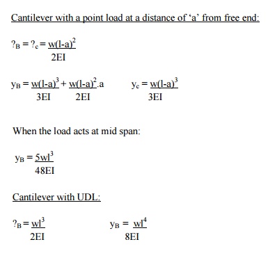
Cantilever beams - problems
Cantilever with a point load at the free end:
Mx
= - w.x
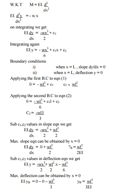
A
cantilever of length carries a concentrated load 'W' at its free end.
Draw shear force and bending moment.
Solution:
At a section a distance x from
free end consider the forces to the left, then F = -W (for all values of x) -ve
sign means the shear force to the left of the x-section are in downward
direction and therefore negative
Taking moments about the section gives (obviously to the left
of the section)
M = -Wx (-ve sign means that the
moment on the left hand side of the portion is in the anticlockwise direction
and is therefore taken as -ve according to the sign
convention)
so that the maximum bending moment occurs at the fixed end
i.e. M = -W l
Simplysupported beam -problems
Simply
supported beam subjected to a central load (i.e. load acting at the mid-way)
By symmetry the reactions at the
two supports would be W/2 and W/2. now consider any section X-X from the left
end then, the beam is under the action of following forces.
.So the shear force at any X-section would be = W/2 [Which is
constant upto x < l/2]
If we consider another section Y-Y which is beyond l/2 then
for all values greater = l/2
SSB with
central point load:
Overhanging beams - problems
In the problem given below, the
intensity of loading varies from q1 kN/m at one end to the q2 kN/m at the other
end.This problem can be treated by considering a U.d.i of intensity q1 kN/m
over the entire span and a uniformly varying load of 0 to ( q2- q1)kN/m over
the entire span and then super impose teh two loadings.
Point of Contraflexure:
Consider the loaded beam a shown
below along with the shear force and Bending moment diagrams for It may be
observed that this case, the bending moment diagram is completely positive so
that the curvature of the beam varies along its length, but it is always concave
upwards or sagging.However if we consider a again a loaded beam as shown below
along with the S.F and B.M diagrams, then
It may be noticed that for the beam loaded as in this case,
The bending moment diagram is
partly positive and partly negative.If we plot the deflected shape of the beam
just below the bending moment
This diagram shows that L.H.S of the beam �sags'
while the R.H.S of the beam �hogs'
The point C on the beam where the
curvature changes from sagging to hogging is a point of contraflexure.
OR
It corresponds to a point where
the bending moment changes the sign, hence in order to find the point of
contraflexures obviously the B.M would change its sign when it cuts the X-axis
therefore to get the points of contraflexure equate the bending moment equation
equal to zero.The fibre stress is zero at such sections
Note: there can be more than one point of
contraflexure
Related Topics